
E1703C Modular 5-Axis CNC Controller
Users Manual
© 2026 by HALaser Systems GmbH
1
E1703C Modular 5-Axis CNC Controller
Users Manual
© 2026 by HALaser Systems GmbH
1

Table of Contents
1 Copyright.........................................................................................................................................................................................................4
2 History..............................................................................................................................................................................................................6
3 Safety................................................................................................................................................................................................................7
4 Overview.........................................................................................................................................................................................................8
4.1.1 E1703C CNC Controller Baseboard...............................................................................................................................8
4.1.2 E1703C LP8 Extension Board...........................................................................................................................................8
4.1.3 E1703C Digi I/O Extension Board...................................................................................................................................9
5 Position Within The System..................................................................................................................................................................10
6 Boards And Connectors.........................................................................................................................................................................11
6.1.1.1 Ethernet Configuration With Windows 10..............................................................................................12
6.1.1.2 Ethernet Configuration With Windows 11..............................................................................................13
6.1.1.3 Ethernet Configuration With Linux.............................................................................................................14
6.1.2 USB.............................................................................................................................................................................................15
6.1.3 Power........................................................................................................................................................................................15
6.1.4 Power LED...............................................................................................................................................................................16
6.1.5 User LEDs................................................................................................................................................................................16
6.1.6 Operation LED.......................................................................................................................................................................17
6.1.7 Input State LEDs...................................................................................................................................................................17
6.1.8 microSD-Card........................................................................................................................................................................17
6.1.10 Opto-Configuration..........................................................................................................................................................22
6.1.11 Extension Connectors.....................................................................................................................................................22
6.1.12 Reset-Button.......................................................................................................................................................................24
6.2.1 MO LED....................................................................................................................................................................................25
6.2.2 Laser Signals...........................................................................................................................................................................25
6.2.3 Extension Connectors........................................................................................................................................................26
7 Quick Start into E1703C........................................................................................................................................................................31
8 ASCII Command Interface.....................................................................................................................................................................32
8.1 General Commands.......................................................................................................................................................................32
8.2 Configuration Commands...........................................................................................................................................................32
8.3 Hardware Commands...................................................................................................................................................................34
10.1 General G-Code Characters....................................................................................................................................................48
10.2 Supported “G”-codes...................................................................................................................................................................48
10.3 Supported “M”-codes..................................................................................................................................................................49
10.4 Supported “T”-codes...................................................................................................................................................................51
10.5 Control Protocol...........................................................................................................................................................................52
APPENDIX A – Wiring between E1703C and IPG YLP Series Type B, B1 and B2 fiber laser........................................53
APPENDIX B – Wiring between E1703C and JPT YDFLP series fiber laser (“MOPA”) or IPG YLP Series Type D
fiber laser or Raycus RFL Series fiber laser.........................................................................................................................................54
APPENDIX C – Wiring between E1703C and IPG YLP Series Type E fiber laser...............................................................55
APPENDIX D – Wiring between E1703C and IPG YLP Series Type G fiber laser..............................................................56
APPENDIX E – Wiring between E1703C and IPG YLR Series laser.........................................................................................57
APPENDIX F – Wiring between E1703C and SPI G4 Pulsed Fibre Laser / TRUMPF TruPulse nano series...........58
APPENDIX G – Wiring between E1703C and Raycus fiber laser..............................................................................................60
2

APPENDIX H – Wiring between E1703C and MaxPhotonics MFP fiber laser...................................................................61
APPENDIX I – IDC connector pin numbering....................................................................................................................................62
APPENDIX J – Board dimensions...........................................................................................................................................................63
3

1 Copyright
This document is © by HALaser Systems.
E1703C base- and extension boards, their hardware and design are copyright / trademark / legal trademark of
HALaser Systems GmbH.
IPG and other are copyright / trademark / legal trademark of IPG Laser GmbH / IPG Photonics Corporation.
All other names / trademarks are copyright / trademark / legal trademark of their respective owners.
Portions of the E1703 firmware are based on lwIP 2.1.2 (or newer):
Copyright (c) 2001-2004 Swedish Institute of Computer Science, Copyright (c) 2025 STMicroelectronics
All rights reserved.
Redistribution and use in source and binary forms, with or without modification, are permitted provided that
the following conditions are met:
1. Redistributions of source code must retain the above copyright notice, this list of conditions and the
following disclaimer.
2. Redistributions in binary form must reproduce the above copyright notice, this list of conditions and
the following disclaimer in the documentation and/or other materials provided with the distribution.
3. The name of the author may not be used to endorse or promote products derived from this software
without specific prior written permission.
THIS SOFTWARE IS PROVIDED BY THE AUTHOR ``AS IS'' AND ANY EXPRESS OR IMPLIED WARRANTIES,
INCLUDING, BUT NOT LIMITED TO, THE IMPLIED WARRANTIES OF MERCHANTABILITY AND FITNESS
FOR A PARTICULAR PURPOSE ARE DISCLAIMED. IN NO EVENT SHALL THE AUTHOR BE LIABLE FOR ANY
DIRECT, INDIRECT, INCIDENTAL, SPECIAL, EXEMPLARY, OR CONSEQUENTIAL DAMAGES (INCLUDING,
BUT NOT LIMITED TO, PROCUREMENT
OF SUBSTITUTE GOODS OR SERVICES; LOSS OF USE, DATA, OR PROFITS; OR BUSINESS
INTERRUPTION) HOWEVER CAUSED AND ON ANY THEORY OF LIABILITY, WHETHER IN CONTRACT,
STRICT LIABILITY, OR TORT (INCLUDING NEGLIGENCE OR OTHERWISE) ARISING IN ANY WAY OUT OF
THE USE OF THIS SOFTWARE, EVEN IF ADVISED OF THE POSSIBILITY
OF SUCH DAMAGE.
Portions of the E1703 firmware are based on FatFS R0.12c (or newer):
FatFs module is an open source software to implement FAT file system to small embedded systems. This is a
free software and is opened for education, research and commercial developments under license policy of
following terms.
Copyright (C) 2017, ChaN, all right reserved.
•
The FatFs module is a free software and there is NO WARRANTY.
•
No restriction on use. You can use, modify and redistribute it for personal, non-profit or commercial
product UNDER YOUR RESPONSIBILITY.
•
Redistributions of source code must retain the above copyright notice.
Portions of the E1703 firmware are based on the HAL Driver Package:
Copyright (c) 2025 STMicroelectronics.
4

This software component is provided by STMicroelectronics as part of a software package and applicable
license terms are in the Package_license file. If you received this software component outside of a package or
without applicable license terms, the terms of the BSD-3-Clause license shall apply.
You may obtain a copy of the BSD-3-Clause at: https://opensource.org/licenses/BSD-3-Clause
5

2 History
Date
Changes in document
05/2026
Hardware control commands added
05/2026
Configuration commands added
02/2026
Initial version
6

3 Safety
The hardware described within this document is designed to control a laser scanner system. Laser radiation
may effect a person's health or may otherwise cause damage. Prior to installation and operation compliance
with all relevant safety regulations including additional hardware-controlled safety measures has to be
secured. The client shall solely be responsible to strictly comply with all applicable and relevant safety
regulations regarding installation and operation of the system at any time.
Beside of that some laser equipment can be damaged in case it is controlled with wrong signals or signals
outside a given specification. Thus it is highly recommended to check the output generated by this hardware
using e.g. an oscilloscope to avoid problems caused by wrong configurations. This should be done prior to
putting a system into operation for the first time, whenever some parameters have been changed or whenever
any kind of software update was installed.
The hardware described here is shipped without any cover and without prefabricated equipment for electric
installation. It is intended to be integrated in machines or other equipment. It is not a device for use "as is", but a
component which is intended to be used as part of a larger device, e.g. for integration in a machine with own
housing or within an electrical cabinet. Prior to operation compliance with all relevant electric /
electromagnetic safety regulations including additional hardware-controlled safety measures has to be
secured. The client shall solely be responsible to strictly comply with all applicable and relevant regulations
regarding installation and operation of the system at any time.
The hardware described here is an electrostatic sensitive device. This means it can be damaged by common
static charges which build up on people, tools and other non-conductors or semiconductors. To avoid such a
damage, it has to be handled with care and including all relevant procedures (like proper grounding of people
handling the hardware, shielding/covering to not to let a person touch the hardware unwanted, proper
packaging in ESD-bags, ...). For more information please refer to related regulations and standards regarding
handling of ESD devices. The EMC Directive (2014/30/EU) does not apply to this hardware as it is not intended
for an end user (a person without knowledge of EMC) and as it is not otherwise made available on the market.
The Low Voltage Directive (2014/35/EU) does not apply to this hardware as the voltage supply is below the
50V AC / 75V DC limit.
This control board is considered partly completed machinery in accordance with the EU Machinery Directive
(2006/42/EC). It cannot operate independently and is intended to be integrated into a larger machine or
system. The final integrator is responsible for ensuring that the complete machine or system complies with all
applicable safety and regulatory requirements in the intended market (such as CE- certification).
This document describes the E1703C-hardware but may contain errors and/or may be changed without further
notice.
7

4 Overview
This document describes the E1703C modular CNC controller board family, their electrical characteristics and
usage. It consist of E1703C 5-axis CNC controller baseboard plus optional extension board. Special variant
E1701M is no CNC controller and therefore not covered by this document.
The E1703C CNC controller boards are designed for controlling motion-stage based stepper motor systems
with two to five axes. Depending on the used extension boards (which are optional) they also supply extensive
signals for laser or mechanical tools (like a mill) and external control. The communication between the host
system and the controller boards is done via Ethernet or USB.
When using E1703C CNC controller boards, there is always one baseboard required for proper operation. This
baseboard can be used together with different extension boards that provide additional signals for controlling
the laser marking process. These extension boards are optional and have to be used only in environments
where the additional signals processed by these boards are required. So depending on used type of laser and
requirements, the minimal solution to control a laser marking system may consist of the baseboard only.
An E1703C baseboard can be combined with several extension boards of different types but never with more
than one board of same type.
Different to the E1701 and E1702 series, the E1703 baseboards no longer consist of a stacked pair of boards
but of one single PCB only.
4.1 Features
Following the features of available base- and extension boards are described
4.1.1 E1703C CNC Controller Baseboard
This baseboard can be used to control XY-tables, CNC-mills, XY/XYZ-stages or similar, stepper-motor driven
devices. It can be combined with different extension boards without any restrictions as long as only one
extension of same type is used at the same time. The E1703C baseboard offers following features:
up to 5 stepper axes controllable via step and direction signals
combined CNC motion of 2..5 axes
can use lasers as well as many other mechanical tools for material processing/milling
up to 370 kHz maximum step frequency (jitter-free)
100 Mbit Ethernet connection
secondary buffer with a size of 1000 commands
USB-C interface
realtime processing of laser and motion signals
can control nearly every laser type (this may require extension boards as described below)
500 MHz realtime CPU
support for microSD, microSDHC and microSDXC cards
can be operated without any SD card optionally
continuous list concept, no need to swap between buffers
BeamConstruct PRO license included
4.1.2 E1703C LP8 Extension Board
This board can be used to provide signals for controlling a wide range of laser types. It offers following features:
LP8 8 bit CMOS level parallel digital output e.g. for controlling laser power
LP8 latch CMOS level digital output for usage with IPG(tm) and compatible laser types
Main Oscillator CMOS level digital output for usage with IPG(tm) and compatible laser types
8 bit 0..5V analogue output e.g. for controlling laser power (this output is directly connected to LP8
outputs)
8

two laser CMOS level digital outputs for usage with YAG, CO2, IPG(tm), SPI(tm) and compatible laser
types (outputs can provide PWM frequency, Q-Switch, FPK-pulse, CW/continuously running
frequency, stand-by frequency) running with frequencies of up to 20 MHz
4.1.3 E1703C Digi I/O Extension Board
This board provides additional digital in- and outputs for synchronisation and communication with external
equipment. It offers following features:
8 freely usable digital outputs providing either CMOS level or electrically insulated outputs via
external power supply
8 freely usable digital inputs expecting either CMOS level or electrically insulated inputs via external
power supply
9
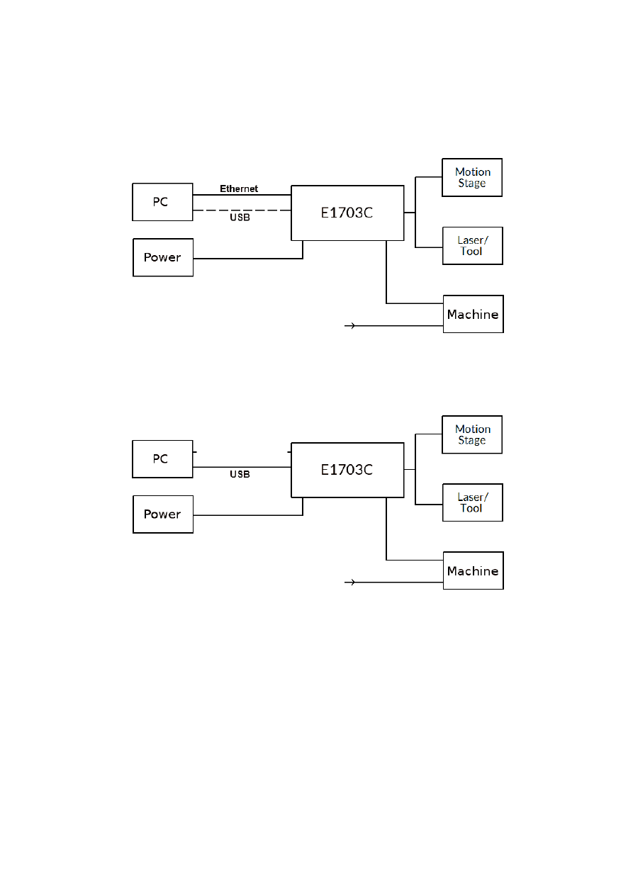
5 Position Within The System
The E1703C CNC controller system can be connected to the host via Ethernet or USB to receive processing
data from BeamConstruct laser marking application or from any other application which makes use of one of
the provided programming possibilities (as described below). When using the Ethernet interface, it optionally
can be connected via USB too. In this case USB connection is only used to retrieve BeamConstruct PRO license
from the board:
Since the 100 Mbit Ethernet typically provides a faster data transfer than USB, this connection type is
preferred.
When using USB connection with such data, time from sending data to the card until marking operation can be
started may be longer, caused by slower USB data transfer:
In both cases the board itself is connected with the stepper motors via separate power drivers to submit fully
synchronous 2D, 3D or 4..5 axis movement information to it. Beside of that it is connected to a laser or any
other tool to submit motion-synchronous data. Additional communication channels between the E1703C CNC
controller board and a connected machine can be done via separate IOs of an extension board.
10
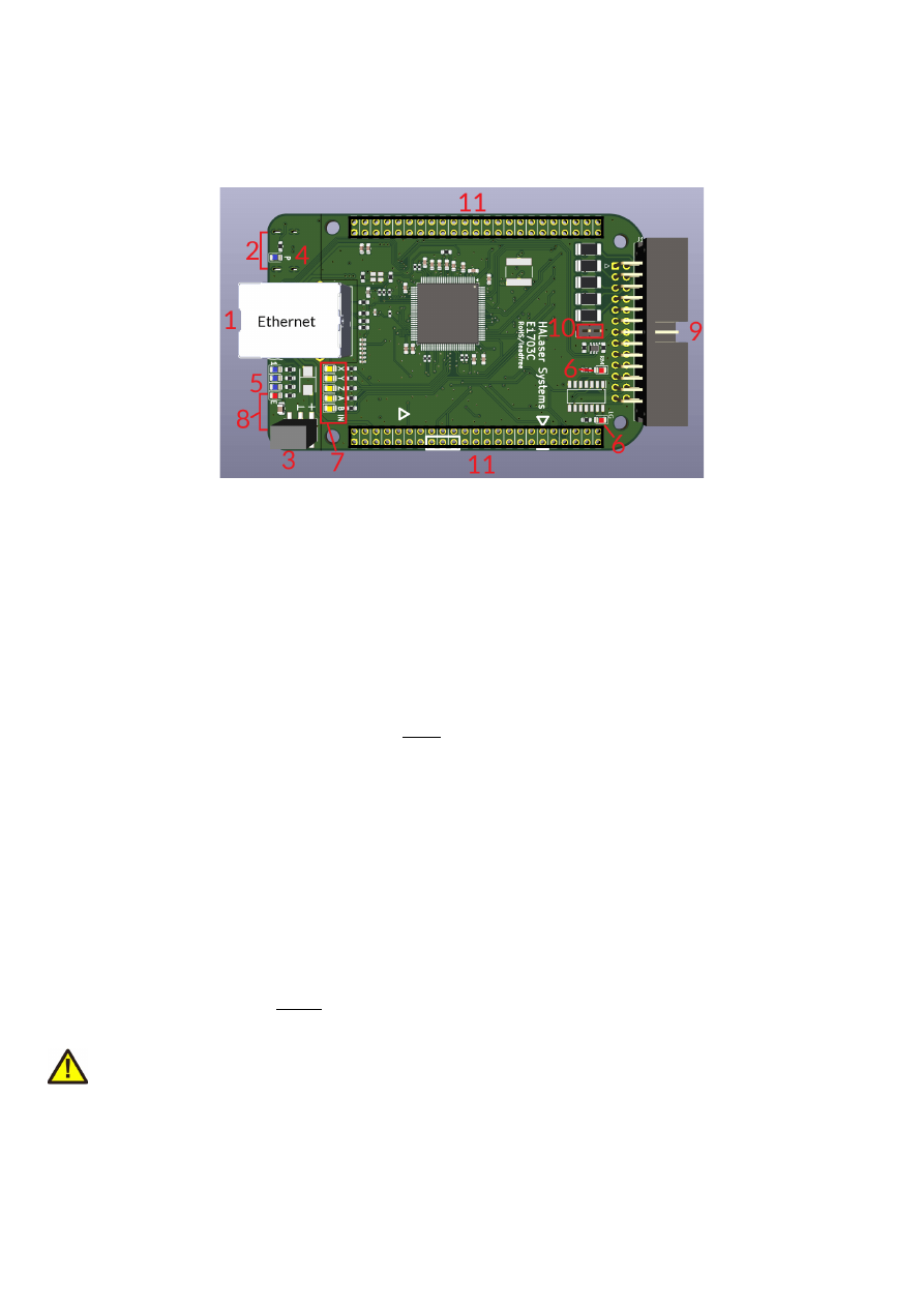
6 Boards And Connectors
6.1 E1703C CNC Controller Baseboard
The E1703C 5-axis CNC Controller Baseboard provides following connectors and interfaces:
1. Ethernet – for communication with the host system, motion and processing information are submitted
via this path
2. USB – via USB-C connector for providing BeamConstruct PRO license to host system and optionally
for submitting processing data from host to E1703C card (in case Ethernet is not used)
3. Power – for providing power in range 9..30V
4. Power LED – lights when power is available
5. User LEDs – show operational and error states of card
6. Operation LEDs – different LEDs that show the operational states
7. Input state LEDs – 5 LEDs showing current state of limit/reference inputs
8. optional microSD-card (on bottom side) – storage place for firmware and extended configuration file,
can be used to upgrade firmware, to change the card's IP and other things more
9. Stepper motor and laser/tool signals – white 26 pin laser and motion signal output connector
10. Opto-Configuration - choose operation mode for limit-inputs
11. Extension connectors – extension boards can be placed here in order to add some more functionality
and hardware interfaces to the board
6.1.1 Ethernet
This is a standard RJ45 Ethernet plug for connection of the board with the host system. When the controller
board is accessed via this connection, all scanner and laser data are sent via Ethernet. Thus it is recommended
for security reasons to have a separate machine network that contains the control-PC, the scanner controller
card(s) and other Ethernet-devices for the machine, but has no physical connection to the “outer world”, means
no access to the internet.
By default the E1803C board is using IP 192.168.2.254, thus the Ethernet network the card is connected with
needs to belong to subnet 192.168.2.0/24.
PLEASE NOTE: For security reasons it is highly recommended to not to mix a standard communication network
with an E1703C network or to connect the scanner controller card with a standard network. Here it may be
possible someone else in that network (accidentally) connects to that scanner controller and causes laser
emission.
The IP of the scanner controller can be changed. This is necessary e.g. in case an other subnet has to be used or
in case the E1703C board has to be operated in multi-head environments where more than one card will be
accessed at the same time. The IP can be configured using e1703.cfg configuration file that is placed on
microSD-card. To change the IP, please perform the following steps:
1. disconnect E1703C board from power and USB
11
2. remove microSD-card
3. put microSD-card into a desktop computer, this may require a microSD- to SD-card-adapter
4. open the drive that is assigned to the card
5. open file e1703.cfg using a text editor like Notepad or kwrite
6. add a line or edit an existing line "
ip0=
", here the desired IP has to be appended (as example: when you
want to configure IP 192.168.2.13 the line has to be "
ip0=192.168.2.13
" – without any quotation
signs
7. save the file
8. eject the drive the card is assigned to
9. place the microSD-card in E1703C board (place without the use of force, notice correct orientation
with connectors of SD-card to top!)
10. power up card
There is the possibility to operate the controller without any SD-card inserted. In this case, the confiuration is
saved on-board. For such a scenario, to change the IP of the controller, following steps have to be done:
1. disconnect E1703C board from power and USB
2. remove microSD-card
3. put microSD-card into a desktop computer, this may require a microSD- to SD-card-adapter
4. open the drive that is assigned to the card
5. open file e1703.cfg using a text editor like Notepad or kwrite
6. add a line or edit an existing line "
ip0=
", here the desired IP has to be appended (as example: when you
want to configure IP 192.168.2.13 the line has to be "
ip0=192.168.2.13
" – without any quotation
signs
7. when not already available, add a line “
storeinflash=1
”
8. save the file
9. eject the drive the card is assigned to
10. place the microSD-card in E1703C board (place without the use of force, notice correct orientation
with connectors of SD-card to top!)
11. power up card
12. wait until the Boot/Alive-LED (but not the Processing-LED!) starts blinking regularly
13. turn off power
14. remove microSD-card
15. now the new settings have been applied and the controller can be used without any SD card inserted
When User LEDs do not light up as described below, please check if microSD-card is placed in board correctly.
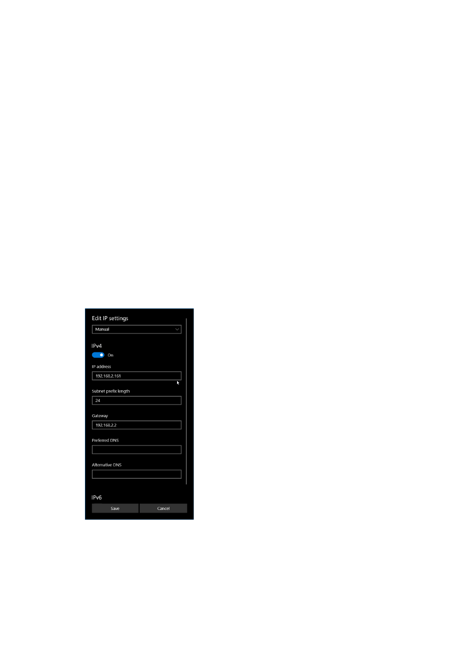
6.1.1.1 Ethernet Configuration With Windows 10
When E1703C scanner controller is accessed via Ethernet, it is recommended to use a separate network for
security reasons. Since the controller is working with a static IP (default is 192.168.2.254) the Ethernet port on
host PC has to be configured with an IP of same subnet in order to allow access to it. For Windows 10 (and
similar) this configuration has to be done using following steps:
1. right-click the network-symbol in your taskbar
2. Select “Open network and internet settings”
3. Select “Ethernet” on the left
4. find the network interface E1703C has to be connected with and select it
5. Click the “Edit” button in section “IP settings”
12
6. now a window opens where “IPv4” has to be turned on and that has to be configured as follows:
There you can specify an IP for your host PC. It has to belong to network 192.168.2.xxx and can be any
number except than 192.168.2.254 (this is already the IP of the scanner card), 192.168.2.0 or
192.168.2.255.
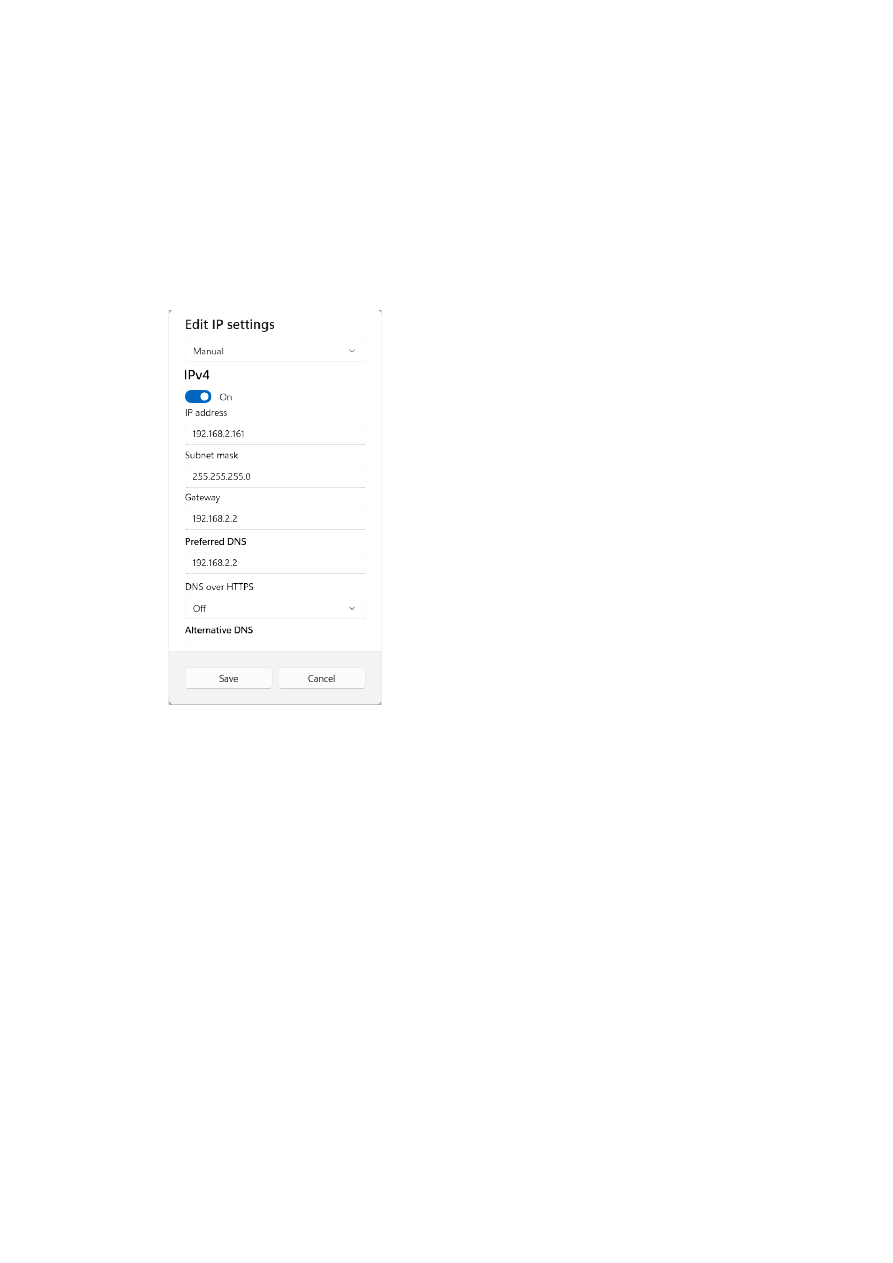
6.1.1.2 Ethernet Configuration With Windows 11
When the E1703 controller is accessed via Ethernet, it is recommended to have a separate network for security
reasons. Since the controller is working with a static IP (default is 192.168.2.254) the Ethernet port on host PC
has to be configured with an IP of same subnet in order to allow access to it. For Windows 11 (and similar) this
configuration has to be done using following steps:
1. right-click the network-symbol in your taskbar
2. Select “Network and internet settings”
3. Select “Ethernet” in the opened list
4. find the network interface E1703C has to be connected with and select it
5. Click the “Edit” button right beside “IP assignment”
6. now a window opens where “Edit IP Settings” has to be switched from “Automatic (DHCP)” to “Manual”
13
7. next “IPv4” has to be turned on and the remaining parameters in this window have to be configured as
follows:
There you can specify an IP for your host PC. It has to belong to network 192.168.2.xxx and can be any
number except than 192.168.2.254 (this is already the IP of the scanner card), 192.168.2.0 or
192.168.2.255.
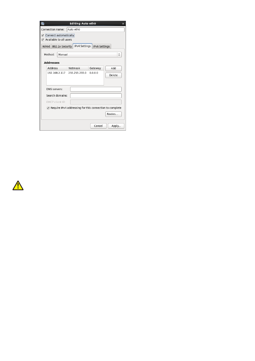
6.1.1.3 Ethernet Configuration With Linux
When E1703C scanner controller is accessed via Ethernet, it is recommended to use a separate network for
security reasons. Since the controller is working with a static IP (default is 192.168.2.254) the Ethernet port on
host PC has to be configured with an IP of same subnet in order to allow access to it. For Linux (with
NetworkManager) this configuration has to be done using following steps:
1. right-click the network-symbol in taskbar
2. click "Edit Connections..."
3. select the "Wired" network interface the scanner card is connected with and press button "Edit"
14
4. go to tab-pane "IPv4 Settings" and configure it as shown below:
There you can specify an IP for your host PC. It has to belong to network 192.168.2.xxx and can be any
number except than 192.168.2.254 (this is already the IP of the scanner card), 192.168.2.0 or
192.168.2.255.
6.1.2 USB
This is a standard USB-C-connector for connection of the board with the host system. It is used to retrieve
BeamConstruct PRO license and optionally – when Ethernet is not used – to send processing data to the card.
PLEASE NOTE: USB is typically slower than a standard 100 Mbit Ethernet connection, so expect less quick
execution in case of complex processing data!
The required device driver is installed automatically during the installation of the HALsetup software package
(Windows) or comes with operating system by default (Linux). E1703C card appears as COM-interface on
Windows using any free number for the port. With Linux it appears as /dev/ttyACMx where "x" is any number.
These numbers are provided by the operating system automatically.
By default USB provides 5V power supply too. So whenever card has to be stopped, both USB and power have
to be disconnected in order to shut it down completely. It is not recommended to use USB as power supply, an
additional, external power should be connected in order to operate E1703C controller correctly. Nevertheless
it might be possible E1703C card can be operated on USB power only. Since this highly depends on the
capabilities of used host system, it has to be evaluated for every particular case.
When the controller has NOT to be powered via USB, there is an option to turn of that power path
permanently. For further details about this possibility, please contact HALaser Systems.
When the controller is connected via USB, a BeamConstruct PRO license is provided via this interface
automatically. This is done without the need to configure anything, and as long as following conditions are true:
•
physical USB connection from controller to host PC exists
•
the COM-port (Windows) has a number smaller than COM20
•
the controller is working and the Alive-LED in blinking
It is also possible to have the USB-connection for license retrieval only and to use the Ethernet-connection to
transfer marking data to the controller, both can exist beside each other.
6.1.3 Power
Power supply for E1703C CNC controller board is done via 6 pin header right beside the Ethernet connector.
Here pairs of pins belong to same power level. An a
ppropriate fuse for circuit protection must be provided by the
external equipment
:
15

NC
GND
+9..+30V
NC
GND
+9..+30V
•
+9..+30V input is marked by a “+” sign
•
GND pins are marked with a “
⊥
” sign
•
the pins not to be connected are not marked
Power has to be supplied via this connector by connecting to a unipolar power supply with a voltage in range
from 9V to 30V DC, max +/- 0.15V tolerance and 1.5A (stabilised and smoothed). Do not apply voltages in
excess of 30V or with inverted polarity to this input. The DC power supply must be grounded.
To avoid high frequency interferences from other electrical equipment or from within the power supply, it may
be necessary to place a ferrite bead at the cable close to the board. Please also check for correct shielding in
respect to the equipment the E1703C card is used within.
ATTENTION: due to the undefined behaviour of some power supplies with high peaks in some specific
situations, the power to the controller never should be toggled just by pulling and reconnecting a cable which is
on power (hot-swap). Always turn off the power the regular way via the power supplies input/a regular switch.
Otherwise this can cause serious damage to the controller card or power supply.
6.1.4 Power LED
This led is lit as soon as the board is on some power. This means it may be functional and could emit any signals
as soon as this LED is on, but it does not necessarily need to work properly since firmware may not be started at
this point. Please refer section “6.1.5 User LEDs” below for LEDs that show functional state of the board.
6.1.5 User LEDs
The real operational state of the card is shown by four additional LEDs described here from inner to outer
position:
Name
Colour
Label on PCB
Boot/Alive
blue
1
Processing
blue
Referencing
blue
Error
red
E
1. Boot- and Alive-LED – this LED is turned on permanently as soon as the firmware of the controller was
loaded successfully. After the startup-process of the firmware has been completed, it starts blinking
slowly. This is an alive-notification, as long as it blinks, the board is working and ready for operation.
During operation the blink frequency may change. Only in case it does not blink for more than 10
seconds, the board has died for some reason and should be restarted.
2. Processing LED – during booting, this LED blinks when data are written from the SD-card to the
internal flash of the controller. When a power-cycle happens during that phase, the written data may
be damaged and it is not possible to operate the controller without an SD-card inserted. In this case it
need to be rebooted again with the SD-card inserted.
In such a situation the Boot/Alive LED is off.
During regular operation of the firmware (means when the Boot/Alive LED is on), this LED is turned on
as long as an operation is in progress and the controller is processing data. This may include motion
operation with the axes or laser emmission. This LED does not correspond to the tool on-off/LaserGate
signal. Comparing to it, it’s also enabled during jumps or wait-cycles when laser is turned off but
processing itself is active.
3. Referencing LED – this LED is lit as long as a the axes are referencing and seeking the reference switch.
4. Error-LED – this LED is turned on in case a fatal error occurs that normally should never happen.
When the Error-LED is turned on during boot-phase (means when the Boot/Alive-LED is off), the
firmware could not be started and the controller is not ready to work.
When the Error-LED is turned on during regular operation (means when the Boot/Alive-LED is
blinking), in most cases board can't continue with operation until the reason for error is removed and
16
the board is restarted. In case this LED is turned on please:
- check if you are using exactly one baseboard
- check if you are using E1703C extension boards only (and no other 3rd party hardware)
- check if you are using latest firmware and host software
- check all connections and cables
- undo your latest changes in hardware and configuration
If these steps do not help, please contact HALaser Systems for further assistance.
6.1.6 Operation LED
These LEDs shows the current marking/milling state of the controller. They consist of two LEDs which can act
completely independent from each other and correspond to the related hardware signal (as described in
section “6.1.9 Stepper motor and control signals”):
•
LG LED – it shows the modulation state of the laser/the activation state of the connected tool and
signal of laser gate output. It corresponds to the LaserGate output signal and is turned on as long as the
laser/the tool is turned on and the laser gate output high. This LED does NOT signal the same like the
Processing LED described above since it will be turned off during jumps.
•
RM LED – it signalises any axis being active and moving. It corresponds to the RunningMotion output
signal.
6.1.7 Input State LEDs
These 5 yellow LEDs show the state of corresponding 5 digital reference inputs. As long as a HIGH signal is
detected on an input, the related LED is turned on. These LEDs can be used to check if a reference input “Ref” is
at high.
On the PCB the LEDs are marked with X, Y, Z, U and V corresponding to the axis names.
For a description of these inputs, please refer to section “6.1.9 Stepper motor and control signals” below.
6.1.8 microSD-Card
The microSD card is the storage place for firmware and configuration files. Here SD, SDHC or SDXC cards are
supported.
The E1703C can be operated with or without an SD-card. For
operation with SD-card
:
•
when the firmware file e1703.fwi has a different version than the last firmware used, this new firmware
is used; on first startup with this new firmware it is loaded onto the on-board flash of the controller,
thus this first boot process may last somewhat longer
•
when the configuration file e1703.cfg contains a parameter “
storeinflash=1
”, ist contents are also
stored controller-internal.
ATTENTION: This parameter should be set only when it is intended to operate the controller without
SD-card. Otherwise the parameters are written on every reset/power-cycle which will age the flash of
the controller prematurely.
For operation
without SD-card
:
•
the controller has to be started at least once with an SD-card inserted and until the Boot/Alive-LED
blinks regularly
•
to also write the configuration of the e1703.cfg file to the internal flash during that operation, this file
needs to contain a line “
storeinflash=1
” during that operation
•
once this is done, the controller can be turned off and the SD-card can be removed; now when it is re-
powered and the Boot/Alive-LED blinks regularly, it is running with these internally stored data
To remove the microSD-card, first disconnect all power from the E1703C board completely (including USB, the
Power LED has to go off). Next press microSD card gently into the board until you can hear a click-noise. Then
you can pull it out of the board. To place a microSD card, the same has to be done in reverse order: place it into
the E1703C board’s card slot and press it gently until a click-noise signals locking of the card. Now the board
can be powered.
E1703C baseboard is shipped with a card containing firmware and configuration files:
17

e1703.fwi – firmware file that is used to operate the board, to be replaced when a firmware update is
provided
e1703.cfg – configuration text file, can be edited using a text editor in order to modify cards
configuration
version.txt – text-file containing information about the used firmware version
To use an other microSD card than the one shipped with the board, following conditions have to be met:
•
FAT32 formatted
•
using only one partition
•
BOOT-flag is set
•
e1703.fwi file available on card
An additional file e1703.cfg can be placed on the card too. It contains plain ASCII text, acts as configuration file
and can contain several parameters and its values which are separated by an equal-sign. Every of the possible
parameter/value pairs has to be located in an own line. Following configuration parameters are possible within
this file:
Parameter
Description
Example
ip0
Configures IP of Ethernet port. Here only IPs in xxx.xxx.xxx.xxx
notation are allowed but no host or domain names.
ip0=192.168.2.100
specifies IP 192.168.2.100
to be used for Ethernet
interface on next startup
rwip0
Configures an IP which has write permission for configuration
parameters when the configuration commands (as described
below) are used
ip0=192.168.2.110
specifies IP 192.168.2.110
as incoming IP which is the
only IP allowed to set
configuration values
passwd
Specifies an access password that is checked when card is
controlled via Ethernet connection. This password corresponds
to password specified with function
E170XC_set_password()
, please refer below for a detailed
description.
When a client computer connects to the card without sending
the correct password, Ethernet connection to this host is closed
immediately.
PLEASE NOTE: this password does not replace any network
security mechanisms and does not give the possibility to operate
E1703C controller via insecure networks or Internet! It is
transferred unencrypted and therefore can be "hacked" easily.
Intention of this password is to avoid collisions between several
E1703C cards that operate in same network and are accessed by
several software instances.
Maximum allowed length of the password is 48 characters. It is
recommended to not to use any language-specific letters.
passwd=cArdPwd2026!
set a password
"cArdPwd2026!"
mipout
Configure a Digi I/O output pin to be used as “mark in progress”-
signal by default; here an output bit number in range 0..7 has to
be configured which will be set to HIGH as long as an operation is
in progress, the value given here can be overwritten by API-
function
E170XC_digi_set_mip_output().
A value 0f
0xFFFFFFFF uses the LaserB output (needs to be configured as
GPO for this), any other value disables this function.
mipout=1
use DOut1 for mark-in-
progress signal
18

Parameter
Description
Example
wetout
Configure a Digi I/O output pin to be used as “wait for external
trigger”-signal by default; here an output bit number in range 0..7
has to be configured which will be set to HIGH as long as an
operation is in progress and the controller is waiting for an
external trigger signal to arrive at ExtStart input, the value given
here can be overwritten by API-function
E170XC_digi_set_wet_output()
. A value 0f 0xFFFFFFFF
uses the LaserB output (needs to be configured as GPO for this),
any other value disables this function.
wetout=0
use DOut0 for mark-in-
progress signal
digiinit
Initialises the digital outputs on firmware start-up with the given
defaults. This overrides the hardware defaults. The default
digital values set here are NOT available on power up but a few
seconds later after firmware has been loaded and started.
digiinit=2
set DOut1 to HIGH initially
and all other outputs to
LOW
digimask
Masks the digital inputs and specifies which inputs can be read.
All input bits which are ignored by this command by setting the
related value to 0, are no longer read.
digimask=253
use only DIn2..DIn7 as
input and ignore DIn0 and
DIn1
tune
Enables special functions and features that are not activated by
default. As parameter a number can be handed over that
specifies the functions to be enabled. Starting with firmware
version 41 the number can also be specified as hexadecimal
value when it is prefixed with “0x”. Following numbers can be
concatenated by adding them:
8 (0x08) – invert LaserGate output to work as active HIGH
signal; when this option is set, logic of LaserGate-LED changes
too, it is on as long as laser is turned off and it is off as long as
laser is on
16 (0x10) – invert LaserA output of LP8 extension to work as
active HIGH signal
64 (0x40) – use LaserA output as GPO (general purpose output
pin); when this flag is set, LaserA output is no longer able to emit
a frequency but can be used as digital output pin; when this value
is set, a tune-value of 0x10 (invert LaserA) is ignored.
128 (0x80) – use LaserB output as GPO (general purpose output
pin); when this flag is set, LaserB output is no longer able to emit
a FPK pulse but can be used as digital output pin; when this value
is set, a tune-value of 0x20 (invert LaserB) is ignored. This flag
has to be set e.g. when LaserA has to be used together with
tunereadyout
or
tunemarkout
parameter.
32768 (0x8000) – invert the mark-in-progress signal of Digi I/O
extension
65536 (0x10000) – invert the wait-external-trigger signal of Digi
I/O extension
16777216 (0x1000000) – inverts the logic of the ExtStart input.
By default, the start-input reacts on a rising edge. When this flag
is set, this is inverted and a falling edge is expected to release an
external trigger.
tune=8
inverts the logic of the
LaserGate output
tune=0x18
logically invert the logic of
both, the LaserGate and
the LaserA output signal
19
Parameter
Description
Example
usb
When this parameter is set to 0, USB interface is disabled
completely. This means it is no longer possible to connect to
E1703C USB serial interface via terminal software or via
BeamConstruct and it is also no longer possible to retrieve
BeamConstruct PRO license via USB. This option can be used to
suppress unwanted access to USB and saves some power.
usb=0
turn off USB interface
eth
This parameter specifies the behaviour of the Ethernet interface.
When it is set to 0, the Ethernet network interface is disabled
completely. This means it is no longer possible to connect to
E1703C via Telnet or via BeamConstruct. This option can be
used to suppress unwanted access to Ethernet, to save little
startup-time and to save some power.
eth=0
– turn off Ethernet
interface completely
6.1.8.1 Firmware Update
As described above the firmware is located on microSD-Card and therefore can be updated easily. There are
two possible usage scenarios where the update procedures are different:
Usage scenario A: The controller is operated
with SD-card inserted
and by using the data from that SD-card:
1. remove the microSD-Card as described above
2. download a new firmware from
https://halaser.systems/download/Firmware/E1703
(the higher the
number in the file name, the newer the firmware is)
3. copy the contents of this ZIP-file to microSD-Card (please take care about E1703.cfg in case it contains
a changed configuration)
4. reinsert microSD-Card as described in previous section
Usage scenario B: The controller is operated with
no SD-card
inserted and by using its internal memory:
1. download a new firmware from
https://halaser.systems/download/Firmware/E1703
(the higher the
number in the file name, the newer the firmware is)
2. copy the contents of this ZIP-file to a microSD-Card
3. reinsert microSD-Card as described in previous section
4. turn on power and wait until the Boot/Alive-LED blinks
5. turn of power
6. remove the microSD-Card as described above
6.1.9 Stepper motor and control signals
The white 26 pin connector provides several signals to control up to five stepper motor axes and connected
tools which can be a laser or any other tool that is able to deal with the related signal. The connector is a white
one to avoid confusion when a LP8 Extension Board is used too. This connector provides following signals:
20

Upper
Row Of
Pins
Signal
Voltage
Remarks
Lower
Row Of
Pins
Signal
Voltage
Remarks
1
Unused, do not connect!
2
5V
5V
3
RefX
CMOS, 0/5V
or 0/V
ext
Reference
inputs
4
RefY
CMOS, 0/5V
or 0/V
ext
Reference
inputs
5
RefZ
CMOS, 0/5V
or 0/V
ext
6
RefA
CMOS, 0/5V
or 0/V
ext
7
RefB
CMOS, 0/5V
or 0/V
ext
8
Do not connect!
9
GND
ext
GND
External
ground
10
GND
GND
Board-
internal
Ground
11
Running
Motion
5V
12
Unused, do not connect!
13
ExtStop
5V
Input
control
signal
14
ExtStart
5V
Input
control
signal
15
StepX
5V
Stepper
pulse
output
signals
16
DirX
5V
Stepper
motor
direction
output
signals
17
StepY
5V
18
DirY
5V
19
StepZ
5V
20
DirZ
5V
21
StepU
5V
22
DirU
5V
23
StepV
5V
24
DirV
5V
25
LaserGate
5V
26
LaserA
5V PWM
GND
ext
depends on opto-configuration as described below. In opto-insulated mode (opto-configuration jumper
not set) external ground has to be connected to this input. Then RefX..RefB work in respect to this external
power add van be driven with an V
ext
of up to 24 V. This is true for the reference inputs only, all other inputs
remain with 0/5V logic levels and can't be driven with any external power.
WARNING: When no opto-insulated mode is selected (opto-configuration jumper is set), do NOT FEED ANY
EXTERNAL POWER into Ref-inputs except the one from 5V output (pin 2), otherwise this would cause damage
to the E1703C board!
The pins 15..24 provide the stepper motor control signals for axes 0..5 (step/direction signals to be used with a
separate, external power driver).
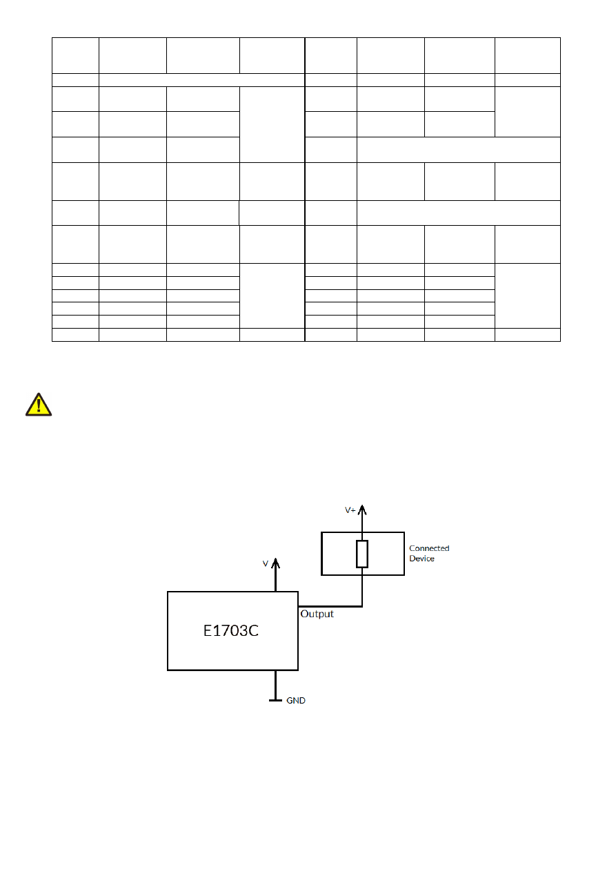
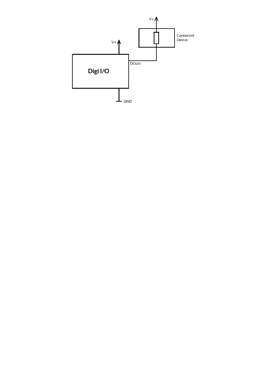
Pins 15..26 all operate in open collector mode and have to be wired as follows:
Here V+ is either V (5V internal, non-insulated mode) or V
ext
(up to 24V external, insulated mode). GND is either
GND (non-insulated mode) or GND
ext
(insulated mode). The internal resistor of the connected device is not
allowed to have less than 530 Ohms (at 24V) or 110 Ohms (at 5V) in order to not exceed the given current
limits as specified below.
The pins 3 to 7 are input pins for axes 0..5 to be used with the reference/homing position.
21
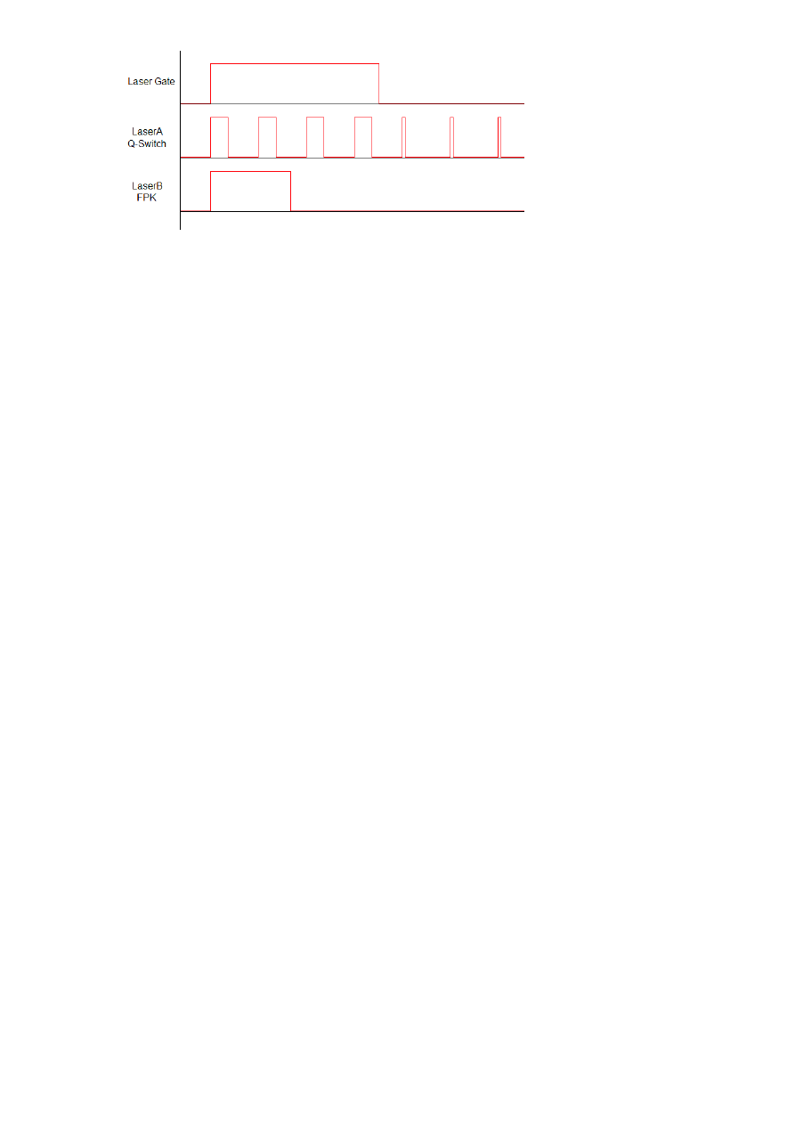
LaserGate provides laser modulation signal, turns on the laser during marks and off during jumps.
RunningMotion provides a HIGH-signal as long as a motion operation is active, means as long as any axis is
moving. This signal can be used as additional safety switch to turn of/inhibit the laser when there is no motion.
LaserA usage depends on software configuration and control, it is able to output a pulse-width modulated
frequency (e.g. for controlling CO
2
lasers), CW/continuously running frequency (e.g. for fiber lasers) or Q-
Switch signal (e.g. for YAG lasers) in range 25 Hz..20 MHz.
Maximum current to be pulled out of each of the outputs is 20 mA.
ExtStart expects a CMOS-level input signal in respect to GND and can be used as external trigger signal to start
operations when a HIGH-signal is detected at input pin.
ExtStop expects a CMOS-level input signal in respect to GND and can be used as external stop-signal in order
to stop a running marking operation by using a HIGH-signal at input pin.
6.1.9.1 Referencing sequence
As the E1703C CNC controller makes use of external stepper motors which can’t persist and provide the
current position, prior to first use (after power-up) or when the motion position was changed manually and
without the controller involved, all axes should be referenced in order to find a defined starting point. For this a
referencing sequence has to be started either via the related API function call (please refer to section “9.1
E1703C Easy Interface Functions”) or via suitable software. When started, a referencing sequence consists of
the following steps:
1. move to the limit switch until it is hit (can be signalled either by LOW or HIGH input level, dependent
on current configuration) using the first referencing speed
2. leave the limit switch until the leave distance has elapsed and using a lower speed; when the switch
can’t be left any more within a reasonable time, referencing fails and is cancelled at this point
3. move again to the limit switch until it is hit (can be signalled either by LOW or HIGH input level,
dependent on current configuration) using the second referencing speed
4. leave the limit switch until the leave distance has elapsed and using a lower speed; when the switch
can’t be left any more within a reasonable time, referencing fails
When the referencing cycle has completed successfully, the controller sets the related axis position to value -2
(which can be changed to any other, suitable value by the controlling software). Now all movement operations
can be done in relation to this fixed, defined position.
When the referencing cycle could not be completed successfully, the axis positions are undefined and should
not be used for any motion operations!
6.1.10 Opto-Configuration
Using this jumper the operation mode for reference inputs RefX..RefB can be chosen. When is is set, the opto-
couplers are powered internally. In this mode it is not working in opto-insulated mode and I/Os are using CMOS
level signals.
When it is not set, external ground has to be provided at GND
ext
pin of the 26 pin connector (as described
above) and the reference inputs are working in electrically insulated, opto-coupled mode with input signal
levels in range 5V..24V.
This opto-insulated mode applies ONLY to the reference inputs, all other signals including step/direction signals
to stepper motor driver are not separated and need to be operated with an external galvanic separation when
this is required.
6.1.11 Extension Connectors
The two extension connectors on each side of the board can be used to place extension boards with additional
peripheral interfaces. The extension connectors are designed to place/remove boards from time to time but
22

they are not intended for constant hardware changes. So changing extension boards repeatedly and often e.g.
as permanent part of a production process is not recommended.
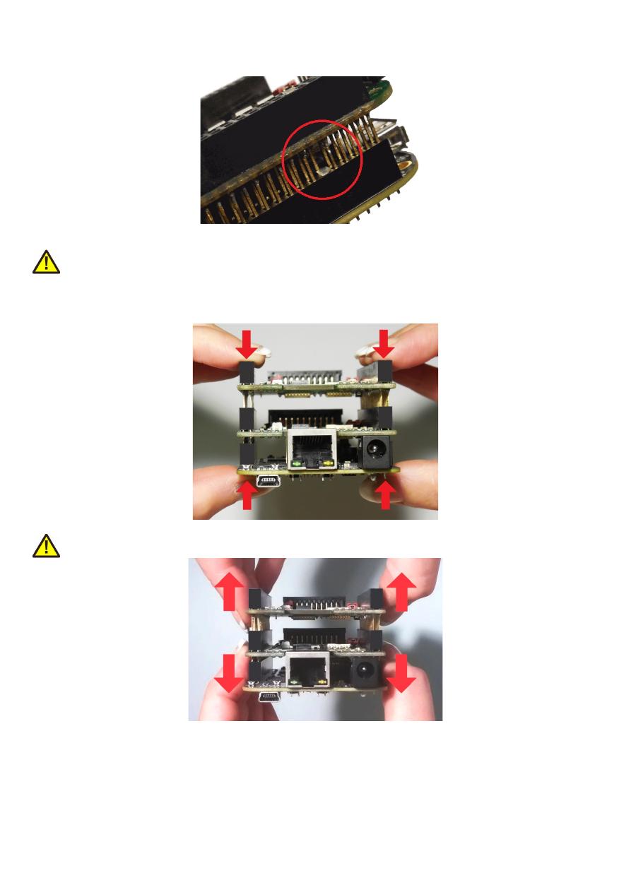
Key pin closed on lower connector and missing in upper board to ensure correct orientation
PLEASE NOTE: when placing a new extension board
1.check correct orientation and position of the key pin which is closed in connector
2.place the pins of the extension boards onto the extension connectors exactly
3.move down the extension board by pressing on its extension connectors gently; DO NOT PRESS THE BOARD
ITSELF BUT ONLY THE CONNECTORS!
PLEASE NOTE: When removing an extension board DO NOT pull on the extension connectors but hold both
boards on their long side directly at the PCBs edges:
Due to of the large number of pins, it is easy to plug in an extension but more difficult to pull it out. So when
removing an extension board, it is recommended to be very slow and to carefully pull each side up just a little bit
to avoid bending of the pins as they exit.
23
6.1.12 Reset-Button
When this button is pressed for at least 20 milliseconds, it restarts the card completely, a current operation is
cancelled, all signals are disabled and all remaining processing data are dropped. After releasing this button, the
board is rebooted and firmware is started again.
24

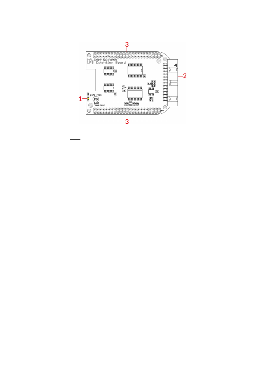
6.2 E1703C LP8 Extension Board
The E1703C LP8 Extension Board provides following features:
1. MO LED – shows state of Main Oscillator output
2. Laser signals – black 26 pin laser output connector which provides signals for controlling a laser
3. Extension connectors – more extension boards can be placed here in order to add some more
functionality and hardware interfaces to the board, please refer to related section in description of
baseboard above
6.2.1 MO LED
This LED is specific to the Master Oscillator output signal described below. As long as the signal is on (HIGH-
signal at output pin), the LED is turned on.
6.2.2 Laser Signals
The black 26 pin connector provides several signals for controlling a laser source. It can be used e.g. together
with YAG, CO
2
, IPG™, fiber and compatible lasers since it provides additional signals and frequencies these laser
types may require for proper operation. To avoid confusion with similar connector used on E1703C Base board
this connector is black.
This connector provides the following signals:
25
Upper
Row Of
Pins
Signal
Voltage
Remarks
Lower
Row Of
Pins
Signal
Voltage
Remarks
1
LP8_0
CMOS, 0/5V,
max 8 mA
2
GND
GND
3
LP8_1
CMOS, 0/5V,
max 8 mA
4
5
LP8_2
CMOS, 0/5V,
max 8 mA
6
5V
5V
7
LP8_3
CMOS, 0/5V,
max 8 mA
8
MO
CMOS, 0/5V,
max 8 mA
Master
Oscillator
9
LP8_4
CMOS, 0/5V,
max 8 mA
10
AOut0
0..5V, max 15
mA
Analogue
output
11
LP8_5
CMOS, 0/5V,
max 8 mA
12
13
LP8_6
CMOS, 0/5V,
max 8 mA
14
15
LP8_7
CMOS, 0/5V,
max 8 mA
16
17
LP8
Latch
CMOS, 0/5V,
max 8 mA
18
5V
5V
19
LaserB
CMOS, 0/5V,
max 14 mA
FPK
20
Connected to
pin 21
21
Connected to
pin 20
22
LaserA CMOS, 0/5V,
max 14 mA
PWM,
frequency or Q-
Switch
23
GND
GND
24
25
5V
5V
26
Laser
Gate
CMOS, 0/5V,
max 14 mA
LP8_0...LP8_7 provide parallel 8 bit output signal (e.g. for power control with IPG(tm)/fiber lasers, waveform
selection for SPI(tm) lasers and other).
LP8 Latch pin signals valid output at LP8_0..LP8_7 and AOut0 by submitting a latch pulse of software-
controlled length.
MO can be used to enable master oscillator (e.g. for IPG(tm)/fiber lasers or compatible).
LaserA usage depends on software configuration and control, it is able to output a pulse-width modulated
frequency (e.g. for controlling CO
2
lasers), CW/continuously running frequency (e.g. for fiber lasers) or Q-
Switch signal (e.g. for YAG lasers) in range 25 Hz..20 MHz.
LaserB can be used for emitting a FPK pulse (e.g. for YAG lasers).
AOut0 pin provides unipolar analogue output for controlling e.g. laser power or additional equipment. This
output depends on LP8_0..LP8_7 outputs, they are electrically connected and therefore can’t have different
values and can’t be controlled by software independently. So when LP8 outputs are all LOW, AOut0 is on 0V.
When LP8 outputs are all HIGH, AOut0 is 5V.
PLEASE NOTE: output of 5V at AOut0 depends on the used power supply. So in case board is powered via USB
and USB power supply delivers less than 5V, maximum output on AOut0 will be less than 5V too. Here is would
be recommended to use the base board with an external power supply that feeds exactly 5V into it.
6.2.3 Extension Connectors
The two extension connectors on each side of the board can be used to place extension boards with additional
peripheral interfaces. For a description of handling and usage of these connectors please refer above.
1 requires hardware-revision 1.1 or newer
26
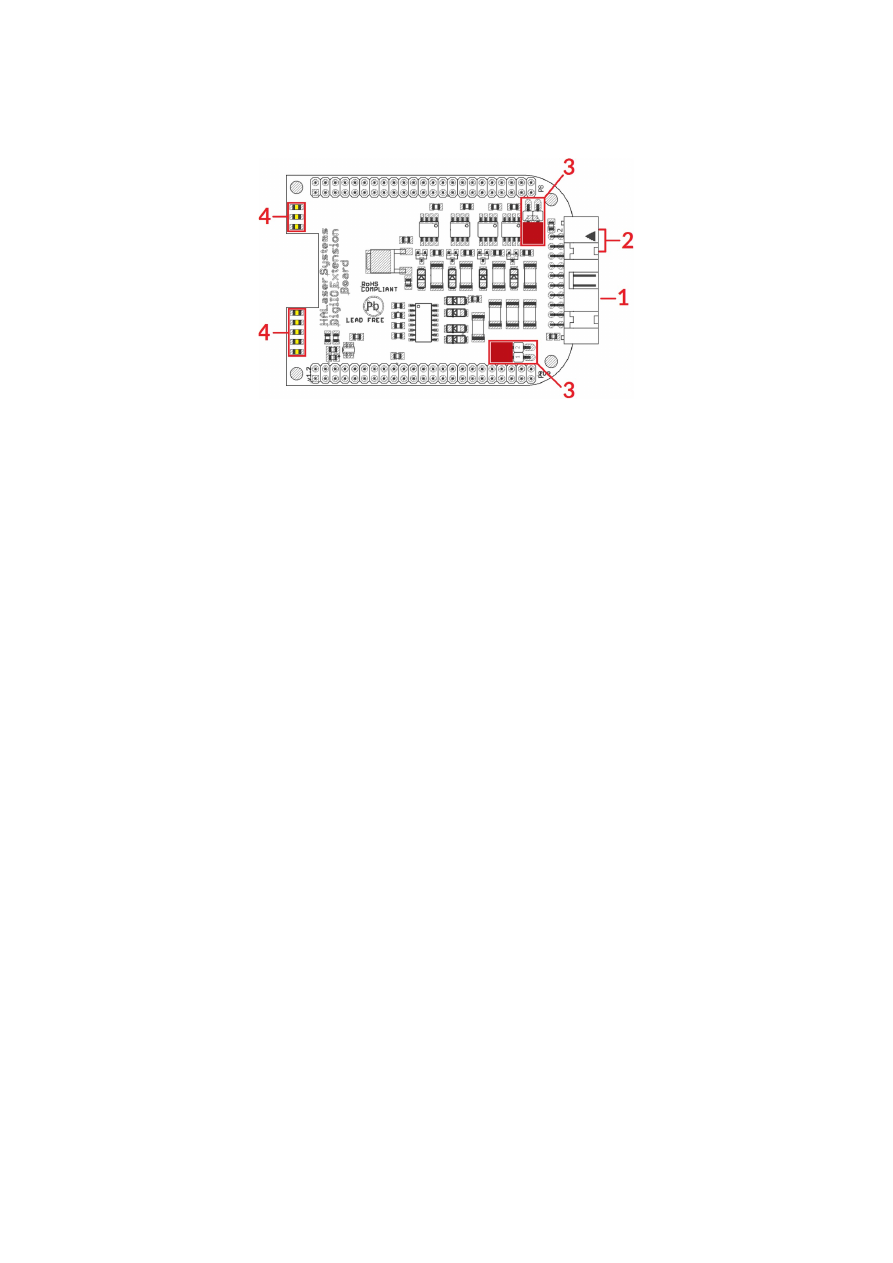
6.3 E1703C Digi I/O Extension Board
The E1703CDigi I/O Extension Board provides following features:
1. Digi I/O – electrically insulated digital in- and outputs
2. optional inputs for 90 degree phase shifted encoders
3. Opto-Configuration – choose operation mode for Digi I/Os
4. Input state LEDs – displaying of HIGH/LOW state of used inputs
In case more extension boards are used on E1703D, Digi I/O extension always has to be placed on top.
6.3.1 Digi I/O
The 20 pin connector provides 8 lines for input and 8 lines for output of digital signals that can work on CMOS
level (non-insulated mode) or via opto-couplers (electrically insulated mode with external power supply)
optionally. The operation mode depends on jumper settings described below. The connector is used as follows:
27
Upper
Row Of
Pins
Signal
Voltage
Remarks
Lower
Row Of
Pins
Signal
Voltage
Remarks
1
V
ext
5..24V
Input voltage to
be used in opto-
insulated mode
only
2
GND
ext
GND
External ground
3
DOut0 CMOS, 0/5V
or 0/V
ext
Default level:
LOW
1)
4
DIn0
CMOS, 0/5V
or 0/V
ext
Encoder-input A1
for marking on-
the-fly
5
DOut1 CMOS, 0/5V
or 0/V
ext
Default level:
LOW
1)
6
DIn1
CMOS, 0/5V
or 0/V
ext
Encoder-input B1
for marking on-
the-fly
7
DOut2 CMOS, 0/5V
or 0/V
ext
Default level:
LOW
1)
8
DIn2
CMOS, 0/5V
or 0/V
ext
Second encoder-
input A2 for
marking on-the-
fly
9
DOut3 CMOS, 0/5V
or 0/V
ext
Default level:
LOW
1)
10
DIn3
CMOS, 0/5V
or 0/V
ext
Second encoder-
input B2 for
marking on-the-
fly
11
DOut4 CMOS, 0/5V
or 0/V
ext
Default level:
HIGH
1)
12
DIn4
CMOS, 0/5V
or 0/V
ext
13
DOut5 CMOS, 0/5V
or 0/V
ext
Default level:
HIGH
1)
14
DIn5
CMOS, 0/5V
or 0/V
ext
15
DOut6 CMOS, 0/5V
or 0/V
ext
Default level:
HIGH
1)
16
DIn6
CMOS, 0/5V
or 0/V
ext
17
DOut7 CMOS, 0/5V
or 0/V
ext
Default level:
HIGH
1)
18
DIn7
CMOS, 0/5V
or 0/V
ext
19
V
5V
Board voltage,
to be used only
when not
operating in
insulated mode
20
GND
GND
Board-internal
ground
1)
Please note the wiring scheme and the resulting, inverted logic below: a level of LOW means, the output is
pulled to GND and a load that is connected from V to this pin is turned on. An level of HIGH means, the output is
pulled to V and a properly wired load if turned off.
V
ext
and GND
ext
depend on opto-configuration as described below. In opto-insulated mode (opto-configuration
jumpers not set) external power supply has to be connected to these inputs. Then DIn0..DIn7 and
DOut0..DOut7 work in respect to this external power.
WARNING: When no opto-insulated mode is selected (opto-configuration jumpers are set), do NOT FEED ANY
POWER into V
ext
, this would cause damage to the E1703C board! In this case V
ext
is equal to V (5V) of the board
and GND
ext
is connected to boards ground GND.
Maximum current for every output is 15 mA when internally powered (non-insulated mode), here it is
recommended to use an external power supply.
Maximum current for outputs DOut0..DOut3 is 50 mA when externally powered (V
ext
in insulated mode).
Signal output lines DOut0..DOut7 operate in open collector mode and have to be wired as follows:
28
Here “DOutx” symbolises one of the digital outputs DOut0..DOut7. V+ is either V (5V internal, non-insulated
mode) or V
ext
(up to 24V external, insulated mode). GND is either GND (non-insulated mode) or GND
ext
(insulated mode). The internal resistor of the connected device is not allowed to have less than 490 Ohms in
order to not exceed the given current limits.
DOut0..DOut3 provide LOW signal level by default, DOut4..DOut7 provide HIGH level by default. These levels
are valid immediately on power-up of the card.
29

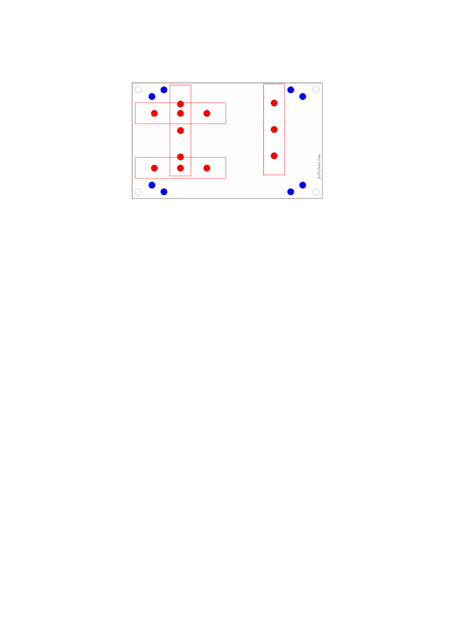
6.4 E170Xbase
The E1703base extension is a mounting help for easy installation on DIN rails/C45 rails and other possibilities
of mechanical integration into machines:
RED
– mounting positions for DIN/C45 rail locks/DIN/C45 rail adapters (bottom side). Pairs of locks can be
mounted in one of 2 possible orientations. Here locks of type Phoenix Contact 1201578 or similar can be used.
With these locks the board then can be clamped on a DIN/C45 rail.
BLUE
– mounting holes for the E1703C CNC controller card on top of the E170Xbase in one of two possible
orientations. These holes are symmetrically arranged so that the board can be mounted by 180 degrees
rotated. Here Hex stands/distance bolts can be screwed in where the controller card is mounted on top.
Mounting procedure for E170Xbase:
1. Identify suitable positions (
RED
) for two DIN/C45 rail locks and mount them on bottom side (two or
three screws from top side into the lock on bottom)
2. Mount hex-stands or distance bolts in at least four of the given mounting holes (
BLUE
).
3. Mount E1703C on top of these hex-stands/distance bolts
4. Clamp the board on your DIN/C45 rail
Without the DIN/C45 rail clamps the board also can be used as top-cover for boards of the E170X-series.
30

7 Quick Start into E1703C
Following a few steps are described that give users the possibility to quick start into usage of E1703C CNC
controller. It makes use of BeamConstruct and the (slow) USB connection. For this quick start manual it is
assumed correct wiring of the controller is already done according to the description above. For more detailed
information about BeamConstruct usage please also refer to quick start manual from
https://halaser.systems/download/manual_quickstart.pdf
and to full user manual which is available at
https://halaser.systems/download/manual.pdf
To start with E1703C controller:
1.
SECURITY CHECK:
The following steps describe how to set up E1703C CNC controller card and how
to control laser equipment and motors with it. Thus all laser safety rules and regulations need to be
respected, all required technical security mechanisms need to be available and active prior to starting
with it.
2. Install latest software version from
https://halaser.systems/download.php
– for Windows this package
contains all required drivers, for Linux no separate drivers are needed.
3. Connect E1703C controller via USB. Power supply via power jack is recommended.
4. Now the Alive-LED should light up and then start blinking after some time. When this does not happen,
please turn power off, check if the microSD-card is placed correctly and then try again.
5. Evaluate the serial interface the controller is connected with – for Windows the Device Manager (can
be found in Control Panel) will list a new COM-port (e.g. “COM3”); for Linux type “dmesg” in console to
find out to which interface it was connected with (typically “/dev/ttyACM0”).
6. Start BeamConstruct laser marking software.
7. Go to menu “Project” “Project Settings...”, then tab-pane “Scanner”.
→
8. Now you can select “E1703C” as controller card.
9. Press the “Configure”-button to get into the settings dialogue for E1703C plug-in.
10. Enter the serial interface name in field “IP/Interface” (e.g. “COM3” or “/dev/ttyACM0”).
11. Leave everything with “OK”.
12. Draw some geometries as described in “BeamConstruct Quick Start Manual”.
13.
SECURITY CHECK:
Next the CNC controller card will be accessed for the first time. That means it is
opened and initialised and all connected equipment may start working now. Thus it is very important to
ensure all security regulations are met and nobody can be injured and no damage can be caused also in
case laser output or other motion starts spontaneously and unexpectedly!
14. Press “F2” or go to menu “Process” “Mark” to open the mark dialogue.
→
15. Start marking by pressing the yellow button with the laser-symbol
31

8 ASCII Command Interface
The E1703C can be accessed via different possibilities. One way to influence the device is via Telnet or USB
serial port where ASCII-control-commands can be send to. This connection can also be used to configure the
device properly in case no SD-card is used.
For this kind of control a Telnet-client has to connect to port 23 using the IP of the node or a terminal
application has to connect to the serial port that is assigned to the USB interface. The Telnet client should work
in passive mode. As soon as the connection is established, commands can be sent to the card. All commands
come with following structure:
cxxxx <parameter(s)>
The commands always start with character “c”. Next four characters identify the command itself. Depending on
the command itself, one or more optional or mandatory parameters may follow. The command always returns
with an "OK" or with an error.
8.1 General Commands
The following commands can be used in all scenarios, they do not depend on a specific operation mode of the
node.
cvers
"
vers
ion" – return version information of the controller card. This command returns a version string
specifying version of hard- and firmware in style
vMM.mm hh
where “
MM
” is the major version of the firmware,
“
mm
” the minor version and “
hh
” specifies the hardware revision of the controller.
8.2 Configuration Commands
Following commands can be used to view and to change the configuration of the E1703C:
cgip0
"
g
et
IP 0"
– get the static IP the node is currently using. The IP is returned as text in format
xxx.yyy.zzz.aaa
csip0 <xxx.yyy.zzz.aaa>
"
s
et
IP 0
" – set a new IP for the node. Please note: this IP is neither stored automatically nor is it set
immediately. To store the IP, the command
cwcfg
has to be used first, to make use of the new IP the node has to
be rebooted.
Please also note: when changing the IP in a way where the subnet is affected, it may be necessary also the
netmask and the gateway have to be reconfigured in order to reflect this new subnet and to let all three
parameters fit to each other. When the node is rebooted without a proper network configuration, the E1703C
may become inaccessible
. In this case please use an SD-card together with a proper e1703.cfg configuration
file to apply a valid configuration to the controller.
When an IP-adress 0.0.0.0 is specified here, the E1703C switches to DHCP-mode, means it tries to retrieve IP
address, gateway and netmask from an DHCP-server in same network. In this case that DHCP-server is
responsible for applying a proper IP address to the E1703C device.
cggw0
"
g
et
g
ate
w
ay
0"
– get the gateway address the node is currently using. The address is returned as text
in format xxx.yyy.zzz.aaa
csgw0 <xxx.yyy.zzz.111>
32

"
s
et
g
ate
w
ay
0
" – set a new gateway address for the E1703C. Please note: this address is neither
stored automatically nor is it set immediately. To store it, the command
cwcfg
has to be used first, to make use
of the new gateway the node has to be rebooted.
Please also note: when changing the gateway in a way where the subnet is affected, it may be necessary also the
netmask and the IP have to be reconfigured in order to reflect this new subnet and to let all three parameters fit
to each other. When the node is rebooted without a proper network configuration, the E1703C
may become
inaccessible
. In this case please use an SD-card together with a proper e1703.cfg configuration file to apply a
valid configuration to the controller.
cgnm0
"
g
et
n
et
m
ask
0"
– get the netmask the node is currently using. The mask is returned as text in format
xxx.yyy.zzz.aaa
csnm0 <xxx.yyy.zzz.111>
"
s
et
n
et
m
ask
0
" – set a new netmask for the node. Please note: this mask value is neither stored
automatically nor is it set immediately. To store it, the command
cwcfg
has to be used first, to make use of the
new netmask the node has to be rebooted.
Please also note: when changing the netmask in a way where the subnet is affected, it may be necessary also
the gateway and the IP have to be reconfigured in order to reflect this new subnet and to let all three
parameters fit to each other. When the node is rebooted without a proper network configuration, the E1703C
may become inaccessible
. In this case please use an SD-card together with a proper e1703.cfg configuration
file to apply a valid configuration to the controller.
cgipw
"
g
et
w
rite-
IP"
– get the static IP which is allowed to have write-accesses to the hardware and from
which it is possible to change configuration parameters via Telnet/serial USB. When no ip is set (0.0.0.0), all
external clients are allowed to write to the hardware, elsewhere only the IP specified here has access.
csipw <xxx.yyy.zzz.aaa>
"
s
et
w
rite-
IP
" – set a new IP which is allowed to have write-accesses to the configuration parameters.
Please note: this IP is neither stored automatically nor is it set immediately. To store the IP, the command
cwcfg
has to be used first, to make use of the new write-IP, the node has to be rebooted.
When an IP-adress 0.0.0.0 is specified here, the write-access limitation is disabled, all connected clients can
change the configuration, no matter from what IP these connections come from. Otherwise only that client can
perform write operations, that comes from the correct IP specified with this command.
cwcfg
"
w
rite
c
on
f
i
g
uration to flash" – save changes in the current configuration in internal flash in order to
persist them and to make them available after next restart. To apply changed configurations, it can be necessary
to reboot the node. This should NOT be done by toggling the power but by calling command
crrrr
. Using this
command ensures a previous save-operation was completed successfully and without any interruption.
clcfg
"list
c
on
f
i
g
uration parameters" – lists all current configuration parameters together with the telnet
command that can be used to set them. This command can be used to get and backup the full configuration of a
E1703C for easy restore or for easy copying to an other node.
crrrr
"
r
eset" – performs a full reset with the node, this command interrupts all connections and running
operations, reboots the E1703C and lets it come back with the default (stored) configuration
33
8.3 Hardware Commands
These commands can be used to access hardware signals directly. When these hardware outputs are set or
unset while a marking operation is running, they may have no effect as they may be overridden immediately.
Thus it is recommended to execute them only when the controller card is idle and no other operations are in
progress. But also in this case, when a hardware output is set to a specific state, any operation (especially
marking cycle) that is executed afterwards, may override that specific state-changes. Following hardware-
specific commands are supported:
cginp
"
g
et
inp
ut" – get the current state of the digital inputs (in case a Digi I/O extension is available). The
input state is returned as a decimal number representing the bitpattern at the inputs. So when e.g. a value "15"
is returned, this means the lower four inputs are set to HIGH while the upper ones are at LOW level
csout <value>
"
s
et
out
put" – set the state of the digital outputs (in case a Digi I/O extension is available). The output
to be set is specified as a decimal number representing the bitpattern. When no parameter is given, the
behaviour is undefined.
Example:
csout 128
– set DOut7 at the Digi I/O extension board to HIGH while all others stay at LOW
cslgt <value>
“
s
et
L
aser
G
a
t
e” – set the state of the LaserGate output either to HIGH (value is set to 1) or to LOW (value is set
to 0).
cslmo <value>
“
s
et
MO
” – set the state of the main oscillator output either to HIGH (value is set to 1) or to LOW (value is set to
0).
cslp8 <value>
“
s
et
LP8
” – set the state of the LP8 output port to the value given as parameter. Here value is allowed to be in
range 0..255, the related bits of the LP8 output are set according to the bitpattern of the specified number.
csao0 <value>
“
s
et
AO
ut
0
” – set the state of the AOut0 analogue output port to the value given as parameter. Here value is
allowed to be in range 0..255 resulting in a correcponendt output value in range 0..V
max
.
34

9 Programming Interfaces
The libe170xc.dll / libe170xc.so shared library provides an own programming interface that gives the possibility
to access and control the E1703C CNC controller card.
9.1 E1703C Easy Interface Functions
These functions belong to the native programming interface of E1703C CNC controller card and should be
used preferential in order to get access to all features and full performance of the card. Functions of E1703C
Easy Interface are either stream commands that are executed in the order they are called, or functions that are
executed immediately.
The E1703C does NOT use the concept of two or more lists that have to be managed and switched by the
calling application. Here all stream commands simply are sent to the card without the need to provide some
additional management information. Output of data is started as soon as possible or when a card-internal
threshold is exceeded. This card-internal triggered output of data can be held back only by calling function
E170XC_set_trigger_point()
as very first so that marking starts only after an external trigger signal was
detected by the card. In this case it may happen that – in case of large amounts of data being sent – the
commands and coordinates have to be stored on host-side and are not sent to the controller. Here it has t obe
ensured enough resources are available on the host system in order to keep these data.
E1703C Easy Interface uses unit “mm” as base for all distance-units and -parameters.
E1703C Easy Interface provides following functions:
unsigned char E170XC_set_connection(const char *address)
This function has to be called as very first. It is used to specify the IP address where the card is
accessible at (in case of Ethernet connection) or the serial interface (in case of USB connection, “COMx” for
Windows and “/dev/ttyACMx” for Linux where “x” is the number of its interface).
It returns a board instance number that has to be used with all following functions.
Please note: this function does only set the connection information, it does not yet open the connection to the
controller! This happens on first call to
E170XC_open_connection()
.
Parameters:
address
– a char-array containing the IP in xxx.yyy.zzz.aaa notation or the name of the COM port to be used
Return: the board instance number or 0 in case of an error
void E170XC_set_password(const unsigned char n,const char *ethPwd)
Sets a password that is used for Ethernet connection of E1703C card. The same password has to be
configured on E1703C configuration file E1703.cfg with parameter "
passwd
" to add an additional level of
security to an Ethernet controlled card.
PLEASE NOTE: usage of this password does NOT provide enough security to control the card via networks that
are accessible by a larger audience, publicly or via Internet! Also when this password is set, the card always
should operate in secured, separated networks only!
Every card and every connection should use an own, unique password that can consist of up to 48 characters
containing numbers, lower- and uppercase letters and punctuation marks. Due to compatibility reasons no
language-specific special character should be used.
When connected via USB serial interface, this password is ignored. In this case no authentication is done.
Parameters:
ethPwd
– the password to be used to authorise at an E1703C card. To reset a local password for connecting to
a card that doesn't has a Ethernet password configured, hand over an empty string "" here
int E170XC_set_debug_logfile(const unsigned char n,const char *path,const
unsigned char flags)
This function can be used during development to check an own application regarding called commands
and their parameters. It lets libe1703c write all function calls into a logfile so that it is possible to evaluate the
real order of commands.
35

Parameters:
n
– the 1-based board instance number as returned by
E170XC_set_connection()
path
– full path to the file which has to be used as debug log file
flags
– a bunch of OR-concatenated flags which specify what function calls have to be written into or filtered
from the log output; when 0x00 is specified here, the log file is kept quite small. When 0x01 is set, all motion-
related function calls are added too, when 0x02 is set, all calls which check the state of the card are added to
the log file.
Return:
E170XC_OK
or an
E170XC_ERROR_
-return code in case of an error
int E170XC_write_debug_logfile(const unsigned char n,const char *format,…)
This function correpsonds to
E170XC_set_debug_logfile()
, it gives the user the possibility to
write own log information into a logfile.
Parameters:
n
– the 1-based board instance number as returned by
E170XC_set_connection()
format
– format specifier as it is used e.g. by printf()
… - data according to the format specifier
Return:
E170XC_OK
or an
E170XC_ERROR_
-return code in case of an error
int E170XC_open_connection(const unsigned char n)
Opens the connection to the CNC controller card.
Parameters:
n
– the 1-based board instance number as returned by
E170XC_set_connection()
Return:
E170XC_OK
or an
E170XC_ERROR_
-return code in case of an error
void E170XC_close(const unsigned char n)
Closes the connection to a card and releases all related resources. After this function was called, no
more commands can be sent to the card until
E170XC_set_connection()
and
E170XC_open_connection()
is called again.
Parameters:
n
– the 1-based board instance number as returned by
E170XC_set_connection()
int E170XC_set_xy_correction(const unsigned char n,const unsigned int
flags,const double gainX, const double gainY, const double rot,const double
slantX, const double slantY)
Sets size correction factor and offset for X and Y direction of working area as well as a rotation and
slant. With this command a matrix set with
E170XC_set_matrix()
will be overwritten.
This is a stream-command, means its parameters are applied at a point in stream that is relative to the other
stream commands and changed values apply only to these vector data and coordinates, which are sent after
calling this function.
Parameters:
n
– the 1-based board instance number as returned by
E170XC_set_connection()
flags
:
•
E170XC_COMMAND_FLAG_XYCORR_MIRRORX
– the output will be mirrored in X-direction
•
E170XC_COMMAND_FLAG_XYCORR_MIRRORY
– the output will be mirrored in Y-direction
gainX
– scale factor in x-direction, 1.0 means no scaling
gainY
– scale factor in y-direction, 1.0 means no scaling
rot
– rotation of whole working area in unit degrees
offsetX
– offset in x-direction in unit bits, 0 means no offset
offsetY
– offset in y-direction in unit bits, 0 means no offset
slantX
– trapezoidal correction along X-axis in range -45..45°
slantY
– trapezoidal correction along Y-axis in range -45..45°
Return:
E170XC_OK
or an
E170XC_ERROR_
-return code in case of an error
36

int E170XC_set_matrix(const unsigned char n,const unsigned int flags,const
double m11,const double m12,const double m21,const double m22)
Specify a 2x2 matrix that contains scaling and rotation corrections for the output. When a
given matrix element parameter has a value smaller or equal -10000000 it is ignored and the previous/default
value is kept at this position in matrix. With this command any correction set with
E170XC_set_xy_correction()
will be overwritten.
This is a stream-command, means its parameters are applied at a point in stream that is relative to the other
stream commands.
Parameters:
n
– the 1-based board instance number as returned by
E170XC_set_connection()
flags
– reserved for future use, set to 0 for compatibility
m11
– first matrix element in first row
m12
– second matrix element in first row
m21
– first matrix element in second row
m22
– second matrix element in second row
Return:
E170XC_OK
or an
E170XC_ERROR_
-return code in case of an error
int E170XC_set_speeds(const unsigned char n,double speed)
Set axis motion speed values to be used for all following vector data and until not replaced by other
speed values. This command sets a path speed for the movement to be performed which – dependent on the
movement direction – results in different absolute speeds of the single axes.
This is a stream-command, means its parameters are applied at a point in stream that is relative to the other
stream commands and changed values apply only to these vector data and coordinates, which are sent after
calling this function.
Parameters:
n
– the 1-based board instance number as returned by
E170XC_set_connection()
speed
– movement speed resulting out of movement of all axes
Return:
E170XC_OK
or an
E170XC_ERROR_
-return code in case of an error
int E170XC_set_laser_mode(const unsigned char n,const unsigned int mode)
Sets the laser mode to be used for all following operations, this value influences the signals emitted at
the connectors of the LP8 extension card. This function has to be called prior to setting any other laser
parameters (like frequency, standby-frequency, power).
This is a stream-command, means its parameters are applied at a point in stream that is relative to the other
stream commands.
Parameters:
n
– the 1-based board instance number as returned by
E170XC_set_connection()
mode
- the laser mode, here one of the following values is possible:
•
E170XC_LASERMODE_CO2
– for controlling CO2 lasers, this mode supports stand-by frequency at
LaserA output (to be set with function
E170XC_set_standby()
) and PWM-modulated frequencies
during marking and for power control (to be set with function
E170XC_set_laser_timing()
)
•
E170XC_LASERMODE_YAG1
– for controlling YAG lasers, this mode supports stand-by and Q-Switch
frequency at LaserA output (to be set with function
E170XC_set_standby()
) and a first pulse killer
signal at output LaserB that is issued on beginning of a mark together with the Q-Switch frequency (to
be set with function
E170XC_set_fpk()
):
37

Here Q-Switch signal is started together with laser gate and FPK pulse. At end of mark when laser gate
is turned off stand-by frequency is emitted at LaserA.
•
E170XC_LASERMODE_CRF
– for controlling lasers that require a continuously running frequency (like
fiber-lasers), this frequency is emitted at LaserA output and can be set and changed by calling function
E170XC_set_standby()
.
•
E170XC_LASERMODE_MOPA
– for fiber lasers which are driven by a main oscillator and power
amplifier and that are power-controlled via LP8 digital port and latch bit
Return:
E170XC_OK
or an
E170XC_ERROR_
-return code in case of an error
int E170XC_set_laser(const unsigned char n,const char on)
Switches the laser on or off independent from any mark or jump commands.
Parameters:
n
– the 1-based board instance number as returned by
E170XC_set_connection()
on
– set to 1 to turn the laser on or to 0 to turn it off
Return:
E170XC_OK
or an
E170XC_ERROR_
-return code in case of an error
int E170XC_jump_abs(const unsigned char n,const uint32_t flags,const double
x,const double y,const double z,const double u,const double v)
Perform a jump (movement with laser/tool turned off) to the given position. This causes a motion from
current position to the one specified by this functions parameters using the jump speed.
This function does not guarantee a movement which describes a straight line from current coordinate position
to the jump-target-coordinates. Instead of this always the fastest way to the new target position is used.
This is a stream-command, means it is executed at a point in stream that is relative to the other stream
commands.
Parameters:
n
– the 1-based board instance number as returned by
E170XC_set_connection()
flags
– a set of OR-concatenated flags which specify which of the handed over coordinate values have to be
used. Here at least one of the flags
E170XC_COMMAND_FLAG_AXIS_X
,
E170XC_COMMAND_FLAG_AXIS_Y
,
E170XC_COMMAND_FLAG_AXIS_Z
,
E170XC_COMMAND_FLAG_AXIS_U
and
E170XC_COMMAND_FLAG_AXIS_V
has to be set. When a flag fr a coordinate is not set, the related value is
ignored.
x
– the x-coordinate in unit mm the tool has to jump to
y
– the y-coordinate in unit mm the tool has to jump to
z
– the z-coordinate in unit mm the tool has to jump to
a
– the a-coordinate in unit mm the tool has to jump to
b
– the b-coordinate in unit mm the tool has to jump to
Return:
E170XC_OK
or an
E170XC_ERROR_
-return code in case of an error
int E170XC_mark_abs(const unsigned char n,const uint32_t flags,const double
x,const double y,const double z,const double u,const double v)
Perform a mark (movement with laser/tool turned on) to the given position. This causes a
movement from current position to the one specified by this functions parameters using the mark speed.
Different to any call to
E170XC_jump_abs()
this function also guarantees a straight line movement is
38

performed from current axis coordinate position to the one specified by this function call. When laser was
turned off before this function is called, laser is turned on at the beginning.
This is a stream-command, means it is executed at a point in stream that is relative to the other stream
commands.
Parameters:
n
– the 1-based board instance number as returned by
E170XC_set_connection()
flags
– a set of OR-concatenated flags which specify which of the handed over coordinate values have to be
used. Here at least one of the flags
E170XC_COMMAND_FLAG_AXIS_X
,
E170XC_COMMAND_FLAG_AXIS_Y
,
E170XC_COMMAND_FLAG_AXIS_Z
,
E170XC_COMMAND_FLAG_AXIS_U
and
E170XC_COMMAND_FLAG_AXIS_V
has to be set. When a flag fr a coordinate is not set, the related value is
ignored.
x
– the x-coordinate in unit mm the tool has to move to
y
– the y-coordinate in unit mm the tool has to move to
z
– the z-coordinate in unit mm the tool has to move to
a – the a-coordinate in unit mm the tool has to move to
b
– the b-coordinate in unit mm the tool has to move to
Return:
E170XC_OK
or an
E170XC_ERROR_
-return code in case of an error
int E170XC_set_trigger_point(const unsigned char n)
Specifies a point in data stream where execution has to stop until an external trigger signal (mark start)
or a manual release of this trigger point is detected. This expects a rising edge on ExtStart input or calling of
function
E170XC_release_trigger_point()
.
This is a stream-command, means it is executed at a point in stream that is relative to the other stream
commands.
Parameters:
n
– the 1-based board instance number as returned by
E170XC_set_connection()
Return:
E170XC_OK
or an
E170XC_ERROR_
-return code in case of an error
int E170XC_release_trigger_point(const unsigned char n)
This function should be called only when a call to
E170XC_set_trigger_point()
was done before.
It acts like an external trigger signal, releases the waiting condition and lets the controller start processing. So
this function provides some kind of software-simulated external start-signal.
This is not a stream-command, it is applied to controller immediately.
Parameters:
n
– the 1-based board instance number as returned by
E170XC_set_connection()
Return:
E170XC_OK
or an
E170XC_ERROR_
-return code in case of an error
int E170XC_set_sync(const unsigned char n,const unsigned int value)
This function sends a synchronisation value "value" to the controller. As soon as marking reaches the
related position in stream, the value returned by
E170XC_get_sync()
changes to the value given here.
When the given value is ensured to be unique, this command can be used to watch the exact execution position
of the current marking operation.
n
– the 1-based board instance number as returned by
E170XC_set_connection()
value
– a unique value which can be used to identify the current progress
Return:
E170XC_OK
or an
E170XC_ERROR_
-return code in case of an error
unsigned int E170XC_get_sync(const unsigned char n)
This function returns the current sync-value as set by function
E170XC_set_sync()
as soon as a
markign operation has reached the related position. When no sync-markers have been set with
E170XC_set_sync()
or when the firs sync-position has not been reached yet, the returned value is
0xFFFFFFFF.
n
– the 1-based board instance number as returned by
E170XC_set_connection()
Return: the current sync-position
39

int E170XC_stop_execution(unsigned char n)
Stops the currently running execution as fast as possible and drops all marking data that still may be
queued. A running motion operation is not cancelled but stopped with the defined deceleration rate so that no
motion steps are lost on the connected motor and no referencing is necessary after such a stop.
This is not a stream command since it controls the current stream of commands.
Parameters:
n
– the 1-based board instance number as returned by
E170XC_set_connection()
Return:
E170XC_OK
or an
E170XC_ERROR_
-return code in case of an error
int E170XC_halt_execution(unsigned char n,unsigned char halt)
Halts or continues the processing and output of marking data. On
halt=1
marking is tried to be
stopped next time the laser/tool would be turned off. This stop is not guaranteed to take place immediately, so
also when this function was called, current process may still continue for some time. Different to a full stop no
vector data are flushed. On continue (
halt=0
) controller continues processing at the point where halt
occurred. When marking is stopped with
E170XC_stop_execution()
the halt-condition is cleared too,
means on next transmission of new marking data they are processed without the need to explicitly continue last
operation.
Parameters:
n
– the 1-based board instance number as returned by
E170XC_set_connection()
halt
– 1 to halt operation next time the laser is off, 0 to continue a previously halted operation
Return:
E170XC_OK
or an
E170XC_ERROR_
-return code in case of an error
unsigned int E170XC_get_startstop_state(const unsigned char n)
This function returns a bit pattern that informs about state of the start and stop input pins.
This is not a stream command since it returns the current state immediately. Here “current state” means the last
known state. When the state changes during this call, it may be possible the previous, no longer actual state is
given back since transmission of data from controller to host is done asynchronously and independent from a
call to this function.
Parameters:
n
– the 1-based board instance number as returned by
E170XC_set_connection()
Return: a bit pattern specifying the current state:
•
bit 0 and 1 (0x00000003) specify if the start input was set after last call of this function, when these
bits are set, a rising edge has been detected at this input; calling this function resets the internal state
of these bits, means when it is called again and when no new rising edge has been detected meanwhile,
these bits will be 0
•
bit 2 and 3 (0x0000000C) specify if the stop input was set after last call of this function, when they are
set, a rising edge has been detected at this input; calling this function resets the internal state of these
bits, means when it is called again and when no new rising edge has been detected at top input
meanwhile, these bits will be low
•
bit 12 (0x00001000) this bit signals the start input is low, as long as this bit is set no start input signal is
detected
int E170XC_get_card_state(const unsigned char n, unsigned int *state)
This function returns a bit pattern that informs about cards current operational state. Here “current
state” means the last known state-change which was not fetched by a call to this commandxc. When the state
changes during this call, it may be possible the previous, no longer actual state is given back since transmission
of data from controller to host is done asynchronously and independent from a call to this function.
The card-states are enqueued internally in order to not to lose any state which may be available for a very short
time only in case of very small and fast marking cycles. So every state change on the controller (which itself
always is caused by the calling application) results in one state change returned by this function. This means for
every marking cycle the application has to wait for two state changes: first wait until this function signals “busy”
(
E170XC_CSTATE_MARKING|E170XC_CSTATE_PROCESSING
), next wait until this function signals “ready”
(0).
40

Same for a referencing operation: first wait until this function signals busy with the
E170XC_CSTATE_IS_REFERENCING
flag set, next wait until this flag is cleared.
During transfer of vector data and motion/laser parameters this function should be called as rarely as possible:
every call of
E170XC_get_card_state()
performs a full cycle of transmission and receiving of data to and
from the controller. Dependent on the current transmission state this may result in submission of a small block
of data which does not uses the full available bandwidth. On excessive use of this function this can slow down
the whole transfer of data.
This is not a stream command since it returns the current state immediately.
Parameters:
n
– the 1-based board instance number as returned by
E170XC_set_connection()
state
– pointer to a variable where the card state has to be written to: a bit pattern of or-concatenated
constants specifying the current state:
•
E170XC_CSTATE_MARKING
- card is currently marking
•
E170XC_CSTATE_PROCESSING
- card has received some data that are enqueued for marking
•
E170XC_CSTATE_HALTED
– the marking process is currently halted and waits for being stopped
completely or being released in order to continue operation
•
E170XC_CSTATE_WAIT_EXTTRIGGER
– the marking process is running but does not do anything
right now as the controller is waiting for a signal at the ExtStart input (or for a call to
E170XC_release_trigger_point()
)
•
E170XC_CSTATE_WAIT_INPUT
– the marking process is running but does not do anything right now
as the controller is waiting for a signal at a digital input
•
E170XC_CSTATE_ERROR
– a fatal operational error happened, such as a failed reference run
•
E170XC_CSTATE_IS_REFERENCING
– the controller is still in referencing mode which may include
movement of axes that are signalled by flag
E170XC_CSTATE_MARKING
additionally.
When the function returns an error code instead of E170XC_OK, this value is undefined and can't be used.
Return:
E170XC_OK
or an
E170XC_ERROR_
-return code in case of an error
int E170XC_delay(unsigned char n,const double delay)
Pause marking for the given time.
This is a stream-command, means it is executed at a point in stream that is relative to the other stream
commands.
Parameters:
n
– the 1-based board instance number as returned by
E170XC_set_connection()
delay
- time to wait until marking continues in unit usec, smallest possible value is 0,5 usecs
Return:
E170XC_OK
or an
E170XC_ERROR_
-return code in case of an error
int E170XC_set_laser_timing(const unsigned char n,const double frequency,const
double pulse)
Set the frequency and pulse-width to be used during marking at LaserA output of LP8 Extension Board.
This is a stream-command, means its parameters are applied at a point in stream that is relative to the other
stream commands.
Parameters:
n
– the 1-based board instance number as returned by
E170XC_set_connection()
frequency
– emitted frequency in unit Hz and in range 25..20000000 Hz
pulse
– pulse width in usec, this value has to be smaller than period length that results out of frequency
Return:
E170XC_OK
or an
E170XC_ERROR_
-return code in case of an error
int E170XC_set_standby(const unsigned char n,const double frequency,const double
pulse,const bool force)
Set the frequency and pulse-width to be used during jumps, as stand-by frequency or as continuously
running frequency at LaserA output of LP8 Extension Board.
This is a stream-command, means its parameters are applied at a point in stream that is relative to the other
stream commands.
Parameters:
n
– the 1-based board instance number as returned by
E170XC_set_connection()
41

frequency
– emitted frequency in unit Hz and in range 25..20000000 Hz. When a value of 0 is given, the
frequency at LaserA output is turned off at end of mark.
pulse
– pulse width in usec, this value has to be smaller than period length that results out of
frequency
force
– when set to true, the new stand-by frequency is not applied the next time the laser is turned off, but
immediately
Return:
E170XC_OK
or an
E170XC_ERROR_
-return code in case of an error
int E170XC_set_fpk(const unsigned char n,const double fpk,const double
yag3QTime)
Set the parameters for first pulse killer signal that is emitted via LaserB output of the baseboard or the
LP8 extension board whenever the laser is turned on; this applies to YAG-modes only and is emitted as one
single pulse at LaserB output.
This is a stream-command, means its parameters are applied at a point in stream that is relative to the other
stream commands.
Parameters:
n
– the 1-based board instance number as returned by
E170XC_set_connection()
fpk
– the length of the first pulse killer signal in usec
yag3QTime
– the length of the first pulse killer signal in usec, this value is used only when laser mode
E1703_LASERMODE_YAG3
is set, elsewhere it is ignored
Return:
E170XC_OK
or an
E170XC_ERROR_
-return code in case of an error
void E170XC_get_version(const unsigned char n,unsigned short *hwVersion,unsigned
short *fwMajorVersion,unsigned short *fwMinorVersion)
Get the hardware and software version of the used board. It is recommended to call this function after
successful connect always and check if used hardware and firmware version is at least a version that is known
to work with own software.
This is not a stream command, it is executed immediately and independent from all other commands.
Parameters:
n
– the 1-based board instance number as returned by
E170XC_set_connection()
hwVersion
– pointer to a variable where the hardware revision/version number is written into
fwVersion
– pointer to a variable where the revision/version number of the firmware running on the board is
written into
int E170XC_get_library_version()
Returns an integer value which is an identifier specifying the version of this shared library. In decimal
notation this identifier uses format "Mmmrrr" where "M" is the major version, "m" the minor version number
and "r" the release count. The bigger the whole returned number is, the newer the library is.
int E170XC_motion_set_steps(const unsigned char n, const unsigned int
flags,const double steps)
Set the factor which defines the relation between steps (increments) of the used stepper motor and the
distance that it travels. This value needs to be specified prior to all other operations in order to allow correct
calculation of all distances and speeds as expected by the other functions as described below. For the E1703C
CNC controller no default value exists, so if no factor is set, motion operations are done with an undefined,
random value which may lead to unexpected results.
The E1703C API always makes use of real distances (in unit mm) and does not expect the calling application to
do the conversion from increments to mm.
Parameters:
n
– the 1-based board instance number as returned by
E170XC_set_connection()
flags
– command flags specifying for which axes the given values have to be applied
(
E170XC_COMMAND_FLAG_AXIS_X
,
E170XC_COMMAND_FLAG_AXIS_Y
,
E170XC_COMMAND_FLAG_AXIS_Z
,
E170XC_COMMAND_FLAG_AXIS_U,
E170XC_COMMAND_FLAG_AXIS_V
)
42

steps
– factor which defines relation between stepper motor steps and travel distance (in unit
increments/mm)
Return:
E170XC_OK
or an
E170XC_ERROR_
-return code in case of an error
int E170XC_motion_set_limits(const unsigned char n,const unsigned int
flags,const double llimit,const double hlimit)
Set motion limits for axis operations. When any follow-up command tries to set values beyond these
limits, these values are clipped to the allowed range set with this function.
Parameters:
n
– the 1-based board instance number as returned by
E170XC_set_connection()
flags
– command flags specifying for which axes the given values have to be applied
(
E170XC_COMMAND_FLAG_AXIS_X
,
E170XC_COMMAND_FLAG_AXIS_Y
,
E170XC_COMMAND_FLAG_AXIS_Z
,
E170XC_COMMAND_FLAG_AXIS_U
,
E170XC_COMMAND_FLAG_AXIS_V
)
llimit
– lower motion limit (in unit mm)
hlimit
– upper motion limit (in unit mm)
Return:
E170XC_OK
or an
E170XC_ERROR_
-return code in case of an error
int E170XC_motion_set_accel(const unsigned char n,const unsigned int flags,const
double accel)
Set the acceleration to be used for start and stop for all motion operations and for the specified axes.
Parameters:
n
– the 1-based board instance number as returned by
E170XC_set_connection()
flags
– command flags specifying for which axes the given values have to be applied
(
E170XC_COMMAND_FLAG_AXIS_X
,
E170XC_COMMAND_FLAG_AXIS_Y
,
E170XC_COMMAND_FLAG_AXIS_Z
,
E170XC_COMMAND_FLAG_AXIS_U,
E170XC_COMMAND_FLAG_AXIS_V
)
accel
– acceleration (in unit mm/sec
2
)
Return:
E170XC_OK
or an
E170XC_ERROR_
-return code in case of an error
int E170XC_motion_reference(const unsigned char n,const unsigned int axis,const
unsigned int mode,const double leaveDist,double speedStep0,double speedStep1)
Starts a referencing operation (=homing sequence) to have a defined position for the axis. The
referencing sequence consists of following steps:
•
move to reference switch (connected to reference-input) with first referencing speed
speedStep0
•
leave the reference switch by the given distance
leaveDist
– when the switch has not been released
after the distance specified by
leaveDist
or after a reasonable time, referencing operation is set as
“failed”
•
move to reference switch (connected to reference-input) with second referencing speed
speedStep1
•
leave the reference switch by the given distance
leaveDist
– when the switch has not been released
after the distance specified by
leaveDist
or after a reasonable time, referencing operation is set as
“failed”
•
set the position of the referenced axis to -1 – when referencing fails for some reason (because it was
interrupted or because the limit switch could not be left within a reasonable time), the position of the
axis will be undefined and
E170XC_get_card_state()
will return an error
E170XC_CSTATE_ERROR
.
This function returns only in case referencing was finished or cancelled due to an error. It can be interrupted by
calling
E170XC_stop_execution()
.
Parameters:
n
– the 1-based board instance number as returned by
E170XC_set_connection()
axis
– specifies which axis has to be referenced, here a value in range 0..4 is expected
mode
– specifies how referencing has to be done exactly, here a bunch of OR-concatenated flags can be handed
over: one of the flags
E170XC_MOTION_REFSTEP_N
(to search for the reference input in negative
43

direction) or
E170XC_MOTION_REFSTEP_P
(to search for the reference input in positive direction)
which optionally can be combined with flag
E170XC_MOTION_REFSTEP_INV_SWITCH
to have
inverted logic on the reference input
leaveDist
– distance (in unit mm or degrees) to move off the reference switch after the switch was found for
the first time
speedStep0
– referencing speed (in unit mm/sec or degrees/sec) to find the reference switch for the first time
(this value can be larger than
speedStep1
but should be small enough to not to overrun the switch)
speedStep1
– referencing speed (in unit mm/sec or degrees/sec) to find the reference switch for the second
time (this value should be smaller than
speedStep0
and is responsible for the accuracy of the
referenced
position)
Return:
E170XC_OK
when operation could be completed successfully,
E170XC_ERROR_REFERENCING
when
referencing has failed for some reason or
E170XC_ERROR_
-return code in case of an other error
int E170XC_motion_set_pos(const unsigned char n,const unsigned int flags,const
double pos)
This function does not cause any movement but resets the current axis position(s) to a new value. It can
be used e.g. after successful referencing to set the initial positions to some own values. All following movement
operations then are done in respect to the position values given here.
n
– the 1-based board instance number as returned by
E170XC_set_connection()
flags
– command flags specifying for which axes the given values have to be applied
(
E170XC_COMMAND_FLAG_AXIS_X
,
E170XC_COMMAND_FLAG_AXIS_Y
,
E170XC_COMMAND_FLAG_AXIS_Z
,
E170XC_COMMAND_FLAG_AXIS_U,
E170XC_COMMAND_FLAG_AXIS_V
)
pos
– the new position value to be set for the specified axis/axes (in unit mm or degrees)
Return:
E170XC_OK
or an
E170XC_ERROR_
-return code in case of an error
int E170XC_lp8_write(const unsigned char n,const unsigned char value)
Sets the LP8_0..LP8_7 outputs of 8 bit laser port of LP8 Extension Board without touching the related
latch output. Total execution time of this command during processing on controller is 1 usec.
This function does not change the value at the analogue AOut0 output of LP8 Extension Board.
Depending on the value of parameter flags this is either a stream-command (means it is executed at a point in
stream that is relative to the other stream commands) or a direct command (means it is executed immediately
on calling).
Parameters:
n
– the 1-based board instance number as returned by
E170XC_set_connection()
value
– the 8 bit value to be set at LP8 port
Return:
E170XC_OK
or an
E170XC_ERROR_
-return code in case of an error
int E170XC_lp8_write_latch(const unsigned char n,const unsigned char on,const
unsigned char value)
Sets the LP8 8 bit laser port of LP8 Extension Board with freely definable delays and toggles the related
latch output automatically; calling this function causes the following sequence of commands:
•
set LP8
•
wait until the LP8 signal has settled
•
toggle the latch bit to apply the LP8 value
•
wait until the latch toggle has been applied
Depending on the value of parameter "
on
" this function may or may not set the analogue AOut0 output
successfully.
This is a stream-command, means it is executed at a point in stream that is relative to the other stream
commands.
Parameters:
n
– the 1-based board instance number as returned by
E170XC_set_connection()
on
– specifies if the latch bit has to be set to HIGH (on=1) or LOW (on=0) on first step, on second step it will
toggle to value
!=on
value
– the 8 bit value to be set at LP8 port
44

Return:
E170XC_OK
or an
E170XC_ERROR_
-return code in case of an error
int E170XC_lp8_a0(const unsigned char n,const unsigned char value)
Sets the analogue output AOut0 of LP8 Extension Board. This also changes the state of LP8_0..LP8_7
outputs and toggles the LP8 latch.
This is a stream-command, means it is executed at a point in stream that is relative to the other stream
commands.
Parameters:
n
– the 1-based board instance number as returned by
E170XC_set_connection()
flags
– handling flags specifying the behaviour of this command,
E170XC_COMMAND_FLAG_STREAM
to use it
as stream command,
E170XC_COMMAND_FLAG_DIRECT
to execute it immediately and independent on current
stream and execution state
value
– the 8 bit value to be set at analogue output port
Return:
E170XC_OK
or an
E170XC_ERROR_
return code in case of an error
int E170XC_lp8_write_mo(const unsigned char n,const unsigned char on)
Sets the main oscillator output MO of LP8 Extension Board to be used with e.g. fiber lasers.
This is a stream-command, means it is executed at a point in stream that is relative to the other stream
commands.
Parameters:
n
– the 1-based board instance number as returned by
E170XC_set_connection()
on
– the state the MO output has to be switched to; PLEASE NOTE: the main oscillator depends on the current
internal state of the laser. Thus turning it on is always possible but turning off the MO is possible only when the
controller is not yet handling the laser-off delay, means it is not possible as long as the laser is turned on. In such
a case this command is ignored.
Return:
E170XC_OK
or an
E170XC_ERROR_
-return code in case of an error
int E170XC_digi_write(const unsigned char n,unsigned int value,const unsigned
int mask)
Sets the 8 bit digital output port of Digi I/O Extension Board.
Parameters:
n
– the 1-based board instance number as returned by
E170XC_set_connection()
mask
– specifies which of the bits in "value" have to be used for setting and clearing output data, only these bits
that are set to 1 in
mask
are changed according to the given
value
value
– the 8 bit value to be set at digital out port
Return:
E170XC_OK
or an
E170XC_ERROR_
return code in case of an error
int E170XC_digi_pulse(const unsigned char n,const unsigned int in_value,const
unsigned int mask,const unsigned int pulses,const double delayOn,const double
delayOff)
Send a sequence of pulses to the 8 bit digital output port of Digi I/O Extension Board.
Parameters:
n
– the 1-based board instance number as returned by
E170XC_set_connection()
mask
– specifies which of the bits in "value" have to be used for setting and clearing output data, only these bits
that are set to 1 in
mask
are changed according to the given
value
value
– the 8 bit value to be set at digital out port
pulses
– specifies how often the output has to be set/cleared
delayOn
– the delay (in unit usec) which has to be issued every time after setting the output, the minimal
resolution of this value is 1 msec
delayOff
– the delay (in unit usec) which has to be issued every time after clearing the output, the minimal
resolution of this value is 1 msec
Return:
E170XC_OK
or an
E170XC_ERROR_
return code in case of an error
45

int E170XC_digi_read(const unsigned char n,unsigned int *value)
Reads the 8 bit digital input port of Digi IO Extension Board.
This is not a stream-command, means it is executed immediately and returns the current state of the digital
inputs.
Parameters:
n
- the 1-based board instance number as returned by
E170XC_set_connection()
value
– pointer to a variable where the current digital input state has to be written into.
When the function returns an error code instead of E170XC_OK, this value is undefined and can't be used.
Return:
E170XC_OK
or an
E170XC_ERROR_
-return code in case of an error
int E170XC_digi_wait(const unsigned char n,const unsigned long value,const
unsigned long mask)
Stop execution and output of data until the given bitpattern was detected at digital inputs of Digit I/O
Extension board. Here parameter
mask
specifies which of the bits at the input have to be checked, they have to
be set to 1. These bits within
mask
that need to be ignored have to be set to 0. Parameter
value
itself defines
the states of the bits that has to be detected at the input to continue processing of data. All bits of
value
that
correspond to bits of
mask
, that are 0, are ignored.
Parameters:
n
- the 1-based board instance number as returned by
E170XC_set_connection()
value
– the expected bitpattern at digital input
mask
– specifies which of the input bits and value bits have to be used for comparison
Return:
E170XC_OK
or an
E170XC_ERROR_
-return code in case of an error
int E170XC_digi_set_mip_output(const unsigned char n,const unsigned int value)
This function can be used to specify which of the digital outputs has to be used for signalling "marking
in progress". When
value
is set to 0xFFFFFFFF, this function is disabled and CNC controller card does not
provide this signal automatically. When the number of the digital output (in range 0..7) is given as
value
, the
related digital output pin is used for "mark in progress" signal.
PLEASE NOTE: here the number (means the count) of one specific output pin has to be given, not a bitpattern
specifying one or more pins!
During operation the selected "mark in progress" pin is HIGH as long as the axes are moving and/or the laser is
on and/or a delay is processed and when marking parameter are processed between these operations. It
becomes LOW as soon as no more marking data are available and current operation is stopped or when
controller is waiting for an external trigger signal (ExtStart).
This is not a stream-commando, when it is called it is applied to current configuration immediately.
Parameters:
n
– the 1-based board instance number as returned by
E170XC_set_connection()
value
– the number of the digital output to be used for this signal
Return:
E170XC_OK
or an
E170XC_ERROR_
-return code in case of an error
int E170XC_digi_set_wet_output(const unsigned char n,const unsigned int value)
This function can be used to specify which of the digital outputs has to be used for signalling "waiting
for external trigger". When
value
is set to 0xFFFFFFFF, this function is disabled and CNC controller card does
not provide this signal automatically. When the number of the digital output (in range 0..7) is given as
value
,
the related digital output pin is used for "waiting for external trigger" signal.
PLEASE NOTE: here the number (means the count) of one specific output pin has to be given, not a bitpattern
specifying one or more pins!
During operation the selected "waiting for external trigger" pin is HIGH as long as the controller is waiting for
an external trigger to be applied at ExtStart input. It becomes LOW as soon as this signal has been detected or
when current operation is stopped.
This is not a stream-command, when it is called, it is applied to current configuration immediately.
Parameters:
n
– the 1-based board instance number as returned by
E170XC_set_connection()
value
– the number of the digital output to be used for this signal
46

Return:
E170XC_OK
or an
E170XC_ERROR_
-return code in case of an error
9.1.1 Error Codes
Most of the functions described above can return an error code in case an operation could not be completed
successfully for any reason. So when it does not return with
E170XC_OK
the error code informs about the
reason for failure:
•
E170XC_ERROR_INVALID_CARD
– a wrong or illegal card number was specified with function
parameter
n
•
E170XC_ERROR_NO_CONNECTION
– a connection to card could not be established
•
E170XC_ERROR_NO_MEMORY
– there is not enough memory available on the host to perform the
requested operation
•
E170XC_ERROR_UNKNOWN_FW
– card is running an unknown and/or incompatible firmware version
•
E170XC_ERROR_TRANSMISSION
– data transmission to card failed
•
E170XC_ERROR_FILEOPEN
– opening of a file failed
•
E170XC_ERROR_FILEWRITE
– writing of data into a file failed
•
E170XC_ERROR_BORD_NA
- a base- or extension board that would be required for a function is not
available
•
E170XC_ERROR_INVALID_DATA
– data or parameters handed over to a function are invalid, out of
range or illegal in current context
•
E170XC_ERROR_UNKNOWN_BOARD
– trying to access a controller board that is not a suitable
controller
•
E170XC_ERROR_FILENAME
– a file name handed over to a function was illegal, it is either too long, has
an illegal or too long file extension, comes with too much sub-directories or contains illegal characters
•
E170XC_ERROR
– an other, unspecified error occurred
•
E170XC_ERROR_NOT_SUPPORTED
– the requested feature or function is not supported by the
current firmware version
•
E170XC_ERROR_NO_DATA_AVAILABLE
– within a function it was tried to receive some data but
there are none available yet
•
E170XC_ERROR_OUT_OF_RANGE
– a function was called with input data that are out of range
•
E170XC_ERROR_REFERENCING
– referencing an axis has failed (e.g. limit switch not found or not left)
47

10 Supported CNC G-Code Commands
Beside the possibility to use the programming interface of the library mentioned in section “9.1 E1703C Easy
Interface Functions”, it is also possible to control the E1703C via G-Code commands, without the need to use
any platform-dependent library. These commands can be sent:
•
by using the USB serial port
•
by using a Telnet-style TCP/IP connection to the contriollers port 20026
In such a scenario, a calling application can watch the execution state either via a digital output which is
configured by using the configuration parameter
wetout
, or via a specific G-Code control protocol that is
described in section 10.5 Control Protocol below.
To allow fast and efficient processing of a CNC file within E1703C, some points have to be noticed. So in order
to improve loading performance it is recommended to:
•
not to have lots of leading or trailing spaces
•
not to make use of large comments
•
have exactly one space between code and related parameter
Beside of that it is mandatory to
•
have a CR/LF between two different codes (so e.g. “
G21 G90
” or “
G21G90
” will result in an error)
•
have no space within a code or within a parameter of a code (so e.g. “
G0 X-0.5 Y.75 Z10
” is valid
but “
G 0 X-0 .5 Y. 75 Z 10
” is not and will result in an error)
•
use a dot as separator in floating point variables (so e.g. “
T1 F6000.0
” is valid but “
T1 F6000,0
” is
not and will result in an error)
Following the G-Code commands are described which are supported.
10.1 General G-Code Characters
Following codes and identifiers are supported by E1702 G-Code interpreter:
Code
Description
Example
G
G-commands, please refer below for a description
G1 X25.75 Y31 Z0.25
M
M-commands, please refer below for a description
M3
T
T-commands, please refer below for a description
T1 F3000
10.2 Supported “G”-codes
Following “G” codes and identifiers are supported by E1702 G-Code interpreter:
Code
Description
Example
G0
Jump to a specified position using unit mm and with a speed
which is at max the value set by command “T1F”. The position to
jump to is specified by up to five parameters X, Y, Z, U and/or V.
This command not necessarily causes an exact linear movement
from the current to the target coordinate, it may perform any
different movement when a faster path is possible.
G0 X0 Y0 Z0 U0 V0
48
Code
Description
Example
G1
Move to a specified position using unit mm and with the speed
that was defined before by using command “T1F”. The position
to move to is specified by up to five parameters X, Y, Z, U and/or
V. Different to G0 this command generates an exact linear
mocement from the current to the target position.
G1 X10 Y10.5 Z11.75
G4
When followed by a parameter „P“ execution is delayed by the
given time (in unit seconds)
G4 P0.002
G21
Set measurement unit to mm, means all positions handed over
e.g. with G0 or G1 will be followed by coordinates in mm. This is
the default setting, the E1703C supports only mm unitsy
G21
G28
Start the referencing process for a single axis. Here the
parameter P specifies with a value in range 0..4 which of the
axes X, Y, Z, A or B have to be referenced.
The referencing process itself is done with the parameters
specified via commands M766, M767, M768, M769, M770
G28 P2
G90
Enable absolute positioning, means all positions handed over
e.g. with G0 or G1 will be followed by absolute coordinates
according to the used coordinate system.
G90
G91
Enable relative positioning, means all positions handed over e.g.
with G0 or G1 will be followed by coordinates that are relative
to the previously used position in used coordinate system.
G91
10.3 Supported “M”-codes
Following “M” codes and identifiers are supported by E1702 G-Code interpreter, here all codes in range
700..799 are specific to the E1702 and contain all laser-related parameters and values:
Code
Description
Example
M3
Set laser on. This command should be sent prior to a marking
operation done with a G1 command.
M3
M5
Set laser off. This command should be sent after a marking
movement with command G1 has been done and when the
marking has to be ended or a jump with G0 has to be performed
next
M5
M700
Set the used laser type. This command is mandatory and has to
be called prior to every laser-related command. As parameter it
expects a decimal number which corresponds to the lasermode-
types
E170X_LASERMODE_xxx
as described in section „9.1
E1703C Easy Interface Functions“
M700 A1073741831
M713
Set first pulse killer value (FPK) for YAG laser types using unit
usec
M713 A10000
M715
Set standby-frequency (at parameter A) in unit Hz and standby-
pulsewidth (at parameter B) in unit nsec.
M715 A50000 B1000
M718
Set laser frequency (at parameter A) in unit Hz and pulsewidth
(at parameter B) in unit usec.
M718 A50000 B10
M719
Switch main oscillator on (1) or off (0). This command can be
used together with SPI or IPG laser types prior to starting a
mark operation to turn MO on or afterwards to turn it off.
M719 A1
49

Code
Description
Example
M750
Change the digital outputs at the digital interface, the
bitpattern that corresponds to the given A-parameter defines
the new HIGH and LOW states of the different pins and the B-
pattern specifies the mask, means it defines which of the output
pins have to be changed.
M750 A3 B15
M751
Change the digital outputs at the LP8 interface, the bitpattern
that corresponds to the given A-parameter defines the new
HIGH and LOW states of the different pins and the B-pattern
specifies the mask, means it defines which of the output pins
have to be changed.
M751 A8 B12
M752
Turn the LP8 latch pin on (1) or off (0). This command can be
used together with MOPA laser types in order to latch-in a
specified 8 bit LP8 port value as set with command M751.
M719 A1
M753
Enable an output to be used to emit a hardware „wait for
externel trigger“ signal that is high as long as the controller is
waiting for an external trigger signal: When the A-value is set to
-1, this function is disabled and the controller card does not
provide this signal automatically. When the number of the
digital output (in range 0..7) is given, the related digital output
pin is used for the "waiting for external trigger" signal.
M753 A4
M754
Enable an output to be used to emit a hardware „marking in
progress“ signal that is HIGH as long as a markign operatin is
running: When the A-value is set to -1, this function is disabled
and the controller card does not provide this signal
automatically. When the number of the digital output (in range
0..7) is given, the related digital output pin is used for the
"markign in progress" signal.
M754 A4
M755
Dynamically set/change tuning-flags according to the
description in section „6.1.8 microSD-Card“, here as A-value the
same value can be specified as described above
M755 A8
M756
Set standby-frequency (at parameter A) in unit Hz and standby-
pulsewidth (at parameter B) in unit nsec. Different to command
M715, which enables the stand-by frequency the next time the
laser is turned off by M5, this command applies and emits this
frequency immediately. So it should be used on initialisation of
the controller.
M756 A50000 B1000
M757
Wait for an external trigger. This can be a signal at the ExtStart
input as well as a “^” control command provided via serial
USB/Telnet connection. When a “wait external trigger” output
is specified by the “wetout” configuration parameter or via
command M753, the related output is at HIGH as long the
controller is waiting.
M758
Wait for a specific bitpattern at the digital inputs of the DigiIOs
extension card’s digital interface, the bitpattern that
corresponds to the given A-parameter defines the HIGH and
LOW states of the different pins and the B-pattern specifies the
mask, means it defines which of the output pins have to be
watched.
M758 A1 B3
M759
This function sends a synchronisation value to the controller. As
soon as marking reaches the
related position in stream, the sync-value returned by the
current state feedback (as described below) is set to this value.
Using this command it is possible to watch at what position the
marking operation currently is.
M759 A13900
50
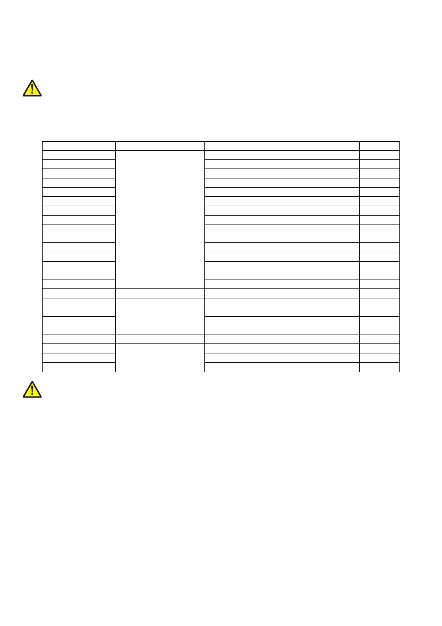
Code
Description
Example
M763
Specify the length of a step-pulse (in unit usec) that has to be
emitted at the step-outputs of the controller during a motion
operation.
This command is handled a stream-command, means a change
of the step-pulsewidth is not applied immediately but at the
time this command is executed regularly in current stream of
commands.
M763 A3.5
M764
Specify the resolution of a stepper axis (in steps/mm) that has
to be used for a specific axis during a motion operation. The A-
parameter specifies the axis in range 0..4 the value has to be set
for, the B-parameter specifies the resolution to be used for that
axis.
This command is handled a stream-command, means a change
of the step-pulsewidth is not applied immediately but at the
time this command is executed regularly in current stream of
commands.
M763 A0 B300
M765
Specify the acceleration and deceleration value to be used for
motion operations of a specific stepper axis (in unit mm/sec²)
that has to be used during a motion operation. The A-parameter
specifies the axis in range 0..4 the value has to be set for, the B-
parameter specifies the acceleration to be used for that axis.
This command is handled a stream-command, means a change
of the step-pulsewidth is not applied immediately but at the
time this command is executed regularly in current stream of
commands.
M763 A0 B300
M766
Specifies if the motion direction of an axis during referencing
has to be inverted (
A1
) or not (
A0
).
M767
Specifies if the input logic of a limit switch has to be inverted
(
A1
) or not (
A0
).
M768
Specifies the first referencing speed (speedStep0) that is used
to initially find the reference switch (in unit mm/min). This
speed is used for the first referencing movement which is
intended to find the reference switch as fast as possible.
Nevertheless here a value should be chosen that allows the axis
to be stopped without leaving the reference swithc on the other
side.
M769
Specifies the second referencing speed (speedStep1) that is
used to exactly detect the reference switch (in unit mm/min).
This speed is used for the referencing movements which leave
and re-enter the switch in order to get its exactl position. So
here a low speed should be set which allows accurate
positioning of the axes.
M770
Specifies the leave-distance during and after referencing (in
unit mm). This leave-distance is used after the reference switch
has been hit.
M770 A2.5
10.4 Supported “T”-codes
Following “T” codes and identifiers are supported by E1702 G-Code interpreter:
51
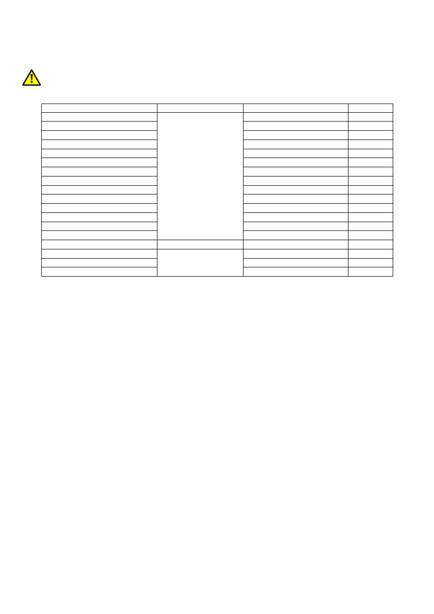
Code
Description
Example
T1
Set motion speed to be used with commands G0 and G1 in unit
mm/min.
T1 F6000.0
10.5 Control Protocol
While the G-Codes, its syntax and meaning are standardised, the communication protocol that is used to
evaluate the current state of the CNC-like operation, is not defined. Here several different control standards
and protocols exist that are not compatible to each other. So this controller makes use of a very common, slim
and easy to interpret control protocol: the one which is known from the GRBL free software. Due to the
different type of controller, there are some changes which are described here.
Following commands can be sent in between a stream of G-code data (different to GRBL they all have to be
completed with a CR/LF in order to let the client software transmit the command to the controller properly):
•
?
- check the current state of processing. Here a string is returned which makes use of following syntax:
<STATE|WPos:x,y,z,u,v|Bf:SEC,PRI|Pn:0x0000|CSt:0x0000>
Here STATE can be “Idle” (when no marking operation is in progress), “Hold” when a marking process is
active but the execution was held by the “!” control command or when it is waiting for a signal at the
ExtStart input. or “Run” when a marking operation is in progress;
WPos is an optional value which returns the current/last position of the axes X, Y, Z, U and V (using
format 0.00);
Bf shows the buffer fill state, here SEC is the secondary buffer, its number specifies how much space is
left in execution buffer for G-Code commands (so this buffer counts the number of commands). PRI is
the primary buffer which specifes the overall freee space in receiving buffer (in unit bytes). So as an
example: a command „G0X100.0Y25.5\r\n“ would consume 15 bytes in primary buffer and – as soon as
it has been processed and forwarded into the secondary buffer – 1 element in buffer „SEC“.
Pn is an optional value which returns the state of the digital inputs at the digital interface(s); this format
is slightly different to the GRBL variant, here a hexadecimal number is given which represents the input
pattern while GRBL lets one single character appear for each known input
Cst returns the state flags that provide much more detailled information about the internal state of the
controller. The bits/flags of this value correspond to the E170XC_STATE_flags as mentioned in section
„9.1 E1703C Easy Interface Functions“
•
!
- halt the current marking operation at the next suitable position, means the next time when the laser
is turned off regularly; when this control command is used, the marking state changes from “Run” to
“Hold”
•
~
- continue a marking operation which was held with the “!” control command
52
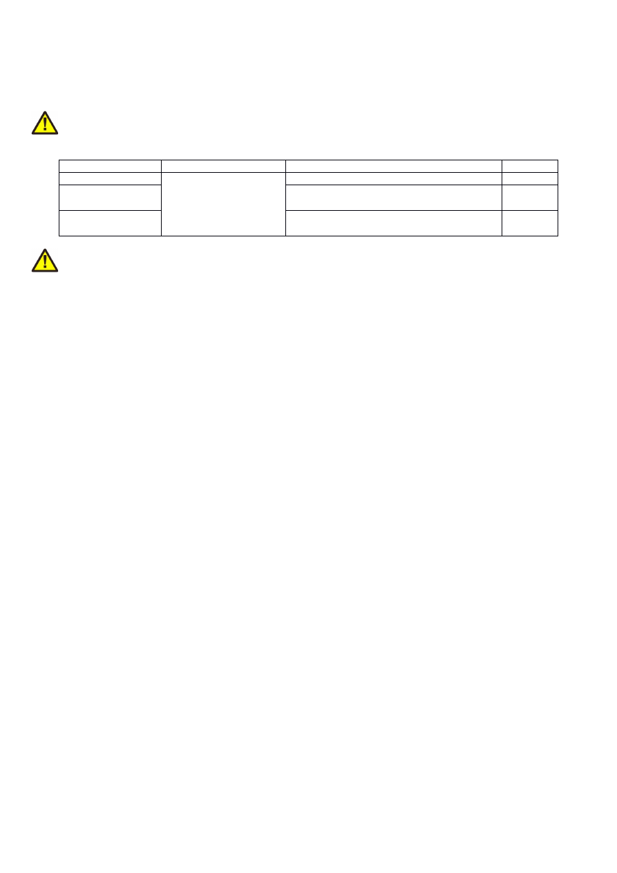
APPENDIX A – Wiring between E1703C and IPG YLP Series
Type B, B1 and B2 fiber laser
PLEASE NOTE: this wiring scheme is a non-binding policy, it may be incorrect due to changes in connected
hardware. So in every case please check this table against specification and wiring documentation of the used
laser!
Variant using LP8 Extension Board and optional Digi I/O Extension Board for laser alarms.
Signal Name
Board
Connector / Pin
IPG Pin
LP0
LP8 Extension Board
Pin 1
Pin 1
LP1
Pin 3
Pin 2
LP2
Pin 5
Pin 3
LP3
Pin 7
Pin 4
LP4
Pin 9
Pin 5
LP5
Pin 11
Pin 6
LP6
Pin 13
Pin 7
LP7
Pin 15
Pin 8
MO / Main
Oscillator
Pin 8
Pin 18
LP8 Latch
Pin 17
Pin 9
LaserA / Frequency
Pin 22
Pin 20
Laser Gate /
Modulation
Pin 26
Pin 19
LaserB
Pin 19
Pin 22 *)
Alarm,
one of DIn0…DIn7
Digi I/O Extension Board
Pin 4, 6, 8, 10, 12, 14, 16 or 18
Pin 16
Alarm,
one of DIn0..DIn7
Pin 4, 6, 8, 10, 12, 14, 16 or 18
Pin 21
*) may require additional power driver since some laser variants consume a current at this input which is higher
than the maximum output allowed
In this wiring-scheme no GND-connections are listed, they have to be added in order to get valid and working
connections.
53

APPENDIX B – Wiring between E1703C and JPT YDFLP
series fiber laser (“MOPA”) or IPG YLP Series Type D fiber
laser or Raycus RFL Series fiber laser
PLEASE NOTE: this wiring scheme is a non-binding policy, it may be incorrect due to changes in connected
hardware. So in every case please check this table against specification and wiring documentation of the used
laser!
Variant using LP8 Extension Board and optional Digi I/O Extension Board for laser alarms.
Signal Name
Board
Connector / Pin
JPT D-SUB25 Pin
LP0
LP8 Extension Board
Pin 1
Pin 1
LP1 / serial data
Pin 3
Pin 2
LP2 / serial clock
Pin 5
Pin 3
LP3
Pin 7
Pin 4
LP4
Pin 9
Pin 5
LP5
Pin 11
Pin 6
LP6
Pin 13
Pin 7
LP7
Pin 15
Pin 8
MO / Main Oscillator
Pin 8
Pin 18
LaserA / Frequency
Pin 22
Pin 20
Laser Gate /
Modulation
Pin 26
Pin 19
LaserB / serial enable
Pin 19
Pin 22
1
)
Alarm,
one of DIn0…DIn7
Digi I/O Extension Board
Pin 4, 6, 8, 10, 12, 14, 16 or 18
Pin 16
Alarm,
one of DIn0…DIn7
Pin 4, 6, 8, 10, 12, 14, 16 or 18
Pin 21
1
) for details regarding double-usage of this pin, please refer to the manual of the laser
In this wiring-scheme no GND-connections are listed, they have to be added in order to get valid and working
connections.
54

APPENDIX C – Wiring between E1703C and IPG YLP Series
Type E fiber laser
PLEASE NOTE: this wiring scheme is a non-binding policy, it may be incorrect due to changes in connected
hardware. So in every case please check this table against specification and wiring documentation of the used
laser!
Variant using LP8 Extension Board and Digi I/O Extension Board for laser alarms with support for APD index
setting via DB-25 serial data interface
Signal Name
Board
Connector / Pin
IPG Pin
LP0
LP8 Extension Board
Pin 1
Pin 1
LP1
Pin 3
Pin 2
LP2
Pin 5
Pin 3
LP3
Pin 7
Pin 4
LP4
Pin 9
Pin 5
LP5
Pin 11
Pin 6
LP6
Pin 13
Pin 7
LP7
Pin 15
Pin 8
MO / Main
Oscillator
Pin 8
Pin 18
LP8 Latch
Pin 17
Pin 9
LaserA / Frequency
Pin 22
Pin 20
Laser Gate /
Modulation
Pin 26
Pin 19
LaserB
Pin 19
Pin 22
1
)
Alarm, one of
DIn0..DIn7
Digi I/O Extension Board
Pin 4, 6, 8, 10, 12, 14, 16 or 18
Pin 16
Alarm, one of
DIn0..DIn7
Pin 4, 6, 8, 10, 12, 14, 16 or 18
Pin 21
Serial Enable
LP8 Extension Board
Pin 7
Pin 24
2
)
Serial Clock
Pin 9
Pin 13
2
)
Serial Data
Pin 11
Pin 10
2
)
1
) may require additional power driver since some laser variants consume a current at this input which is higher
than the maximum output allowed
In this wiring-scheme no GND-connections are listed, they have to be added in order to get valid and working
connections.
55

APPENDIX D – Wiring between E1703C and IPG YLP Series
Type G fiber laser
PLEASE NOTE: this wiring scheme is a non-binding policy, it may be incorrect due to changes in connected
hardware. So in every case please check this table against specification and wiring documentation of the used
laser!
Signal Name
Board
E1703C Connector / Pin
D-SUB25
LP0
LP8 Extension Board
Pin 1
Pin 1
LP1
Pin 3
Pin 2
LP2
Pin 5
Pin 3
LP3
Pin 7
Pin 4
LP4
Pin 9
Pin 5
LP5
Pin 11
Pin 6
LP6
Pin 13
Pin 7
LP7
Pin 15
Pin 8
MO / Main Oscillator
Pin 8
Pin 18
LP8 Latch
Pin 17
Pin 9
LaserA / Frequency
Pin 22
Pin 20
Laser Gate / Modulation
26 pin connector, pin 26
Pin 19
LaserB
Pin 19
Pin 22
GND
Pin 2 or 23
Pin 14
Alarm, one of DIn0…DIn7
Digi IO Extension Board
Pin 4, 6, 8, 10, 12, 14, 16 or 18
Pin 11
Alarm, one of DIn0…DIn7
Pin 4, 6, 8, 10, 12, 14, 16 or 18
Pin 16
Alarm, one of DIn0…DIn7
Pin 4, 6, 8, 10, 12, 14, 16 or 18
Pin 21
56
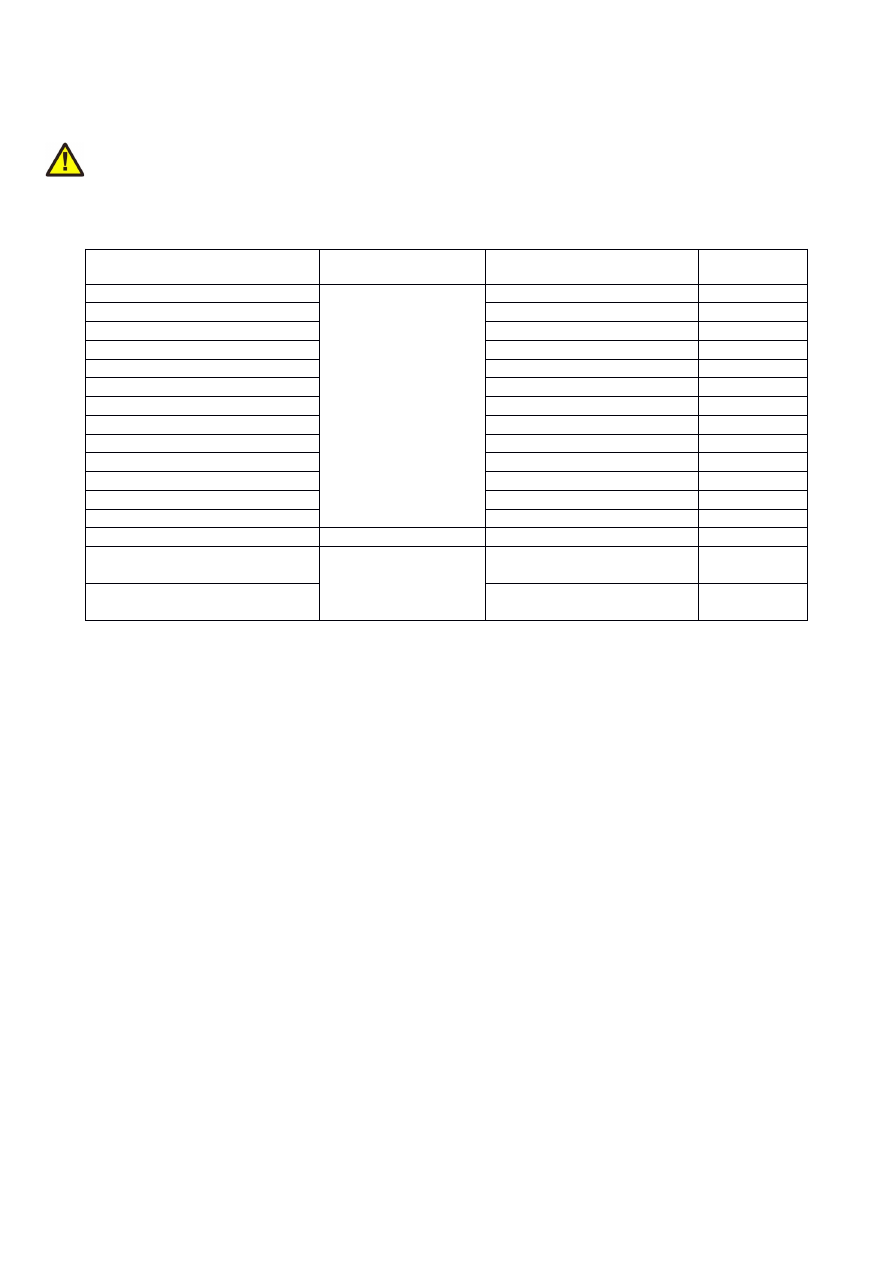
APPENDIX E – Wiring between E1703C and IPG YLR Series
laser
PLEASE NOTE: this wiring scheme is a non-binding policy, it may be incorrect due to changes in connected
hardware. So in every case please check this table against specification and wiring documentation of the used
laser!
Signal Name
Board
Connector / Pin
IPG Pin
AOut0
LP8 Extension Board
Pin 10
Pin 12
1
)
MO / Main
Oscillator
Pin 8
Pin 18
Laser Gate /
Modulation
Pin 26
Pin 15
1
) maximum analogue output voltage of LP8 extension is limited to 5V while this laser type expects 0..10V
range. So this voltage needs to be doubled by some external equipment, elsewhere the laser can be driven with
a maximum of 50% power only
In this wiring-scheme no GND-connections are listed, they have to be added in order to get valid and working
connections.
57
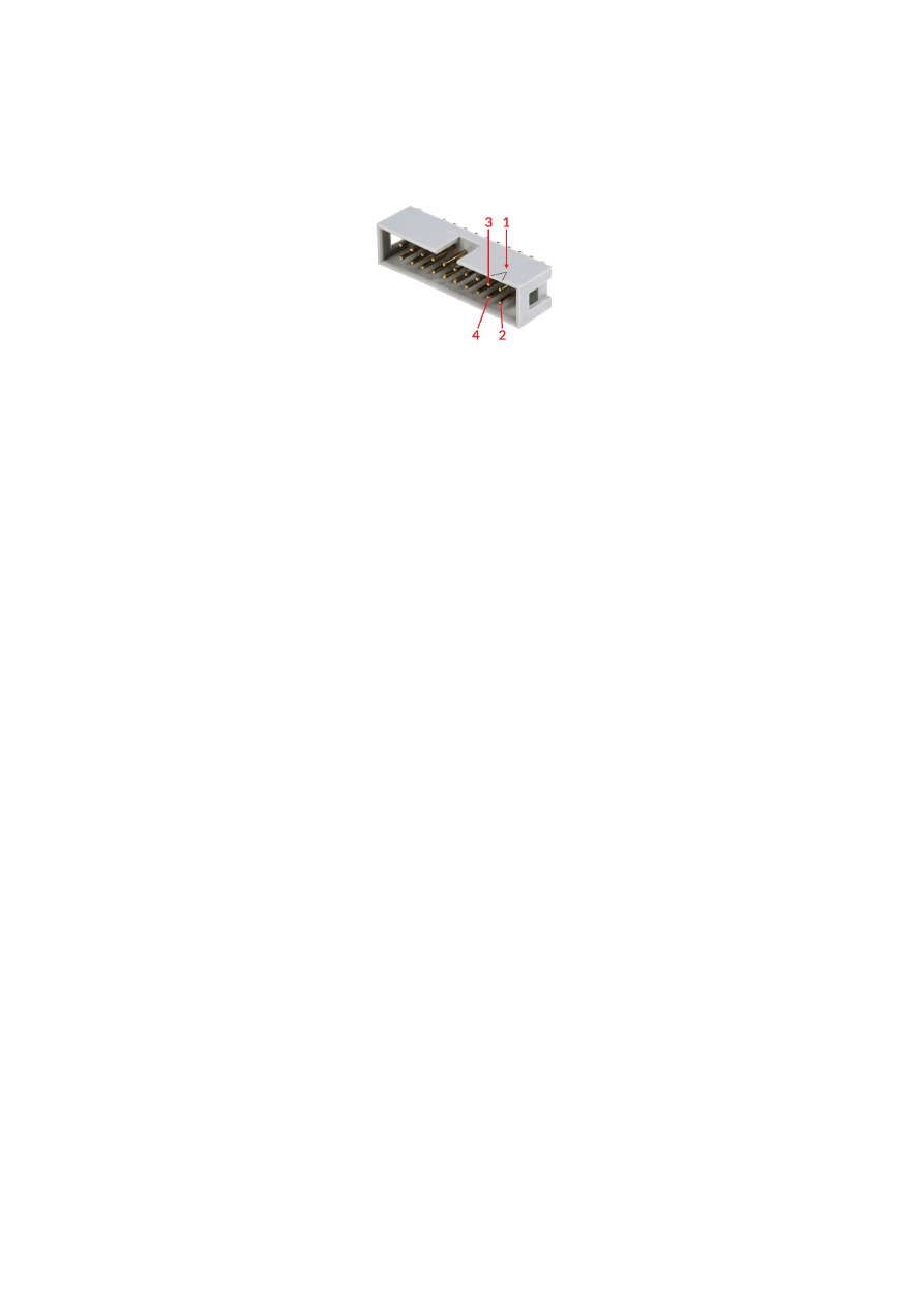
APPENDIX F – Wiring between E1703C and SPI G4 Pulsed
Fibre Laser / TRUMPF TruPulse nano series
PLEASE NOTE: this wiring scheme is a non-binding policy, it may be incorrect due to changes in connected
hardware. So in every case please check this table against specification and wiring documentation of the used
laser!
Variant 1: waveform selected via LP8 outputs of LP8 Extension Board, simmer, power and extended parameter
control via laser controller plug in/serial interface:
Signal Name
Board
Connector / Pin
SPI Laser
Connector Pin
LP0
LP8 Extension Board
Pin 1
Pin 17
LP1
Pin 3
Pin 18
LP2
Pin 5
Pin 19
LP3
Pin 7
Pin 20
LP4
Pin 9
Pin 51
LP5
Pin 11
Pin 52
LP6
Pin 13
Pin 53
LP7
Pin 15
Pin 54
MO / Laser Enable
Pin 8
Pin 7
LP8 Latch
Pin 17
Pin 23
LaserA / Pulse
Trigger
Pin 22
Pin 47
Laser Gate /
Modulation
Pin 26
Pin 5
Alarm,
one of DIn0…DIn7
Digi I/O Extension Board
Pin 4, 6, 8, 10, 12, 14, 16 or 18
Pin 9
Variant 2: waveform selected via digital outputs of Digi I/O Extension Board, simmer, power and extended
parameter control via laser controller plug in/serial interface:
Signal Name
Board
Connector / Pin
SPI Laser
Connector Pin
DOut0
Digi I/O Extension Board
Pin 3
Pin 17
DOut1
Pin 5
Pin 18
DOut2
Pin 7
Pin 19
DOut3
Pin 9
Pin 20
DOut4
Pin 11
Pin 51
DOut5
Pin 13
Pin 52
DOut6
Pin 15
Pin 53
DOut7
Pin 17
Pin 23
Alarm,
one of DIn0…DIn7
Pin 4, 6, 8, 10, 12, 14, 16 or 18
Pin 9
MO / Laser Enable
LP8 Extension Board
Pin 8
Pin 7
LaserA / Pulse
Trigger
Pin 22
Pin 47
Laser Gate /
Modulation
Pin 26
Pin 5
Variant 3: waveform selection, simmer, power and extended parameter control via laser controller plug in/serial
interface:
58
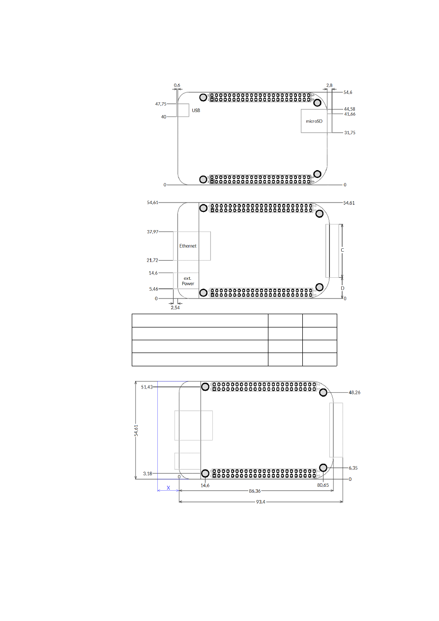
Signal Name
Board
Connector / Pin
SPI Laser
Connector Pin
MO / Laser Enable
LP8 Extension Board
Pin 8
Pin 7
LaserA / Pulse
Trigger
Pin 22
Pin 47
Laser Gate /
Modulation
Pin 26
Pin 5
Alarm,
one of DIn0…DIn7
Digi I/O Extension Board Pin 4, 6, 8, 10, 12, 14, 16 or 18
Pin 9
In these wiring-schemes no GND-connections are listed, they have to be added in order to get valid and
working connections.
59
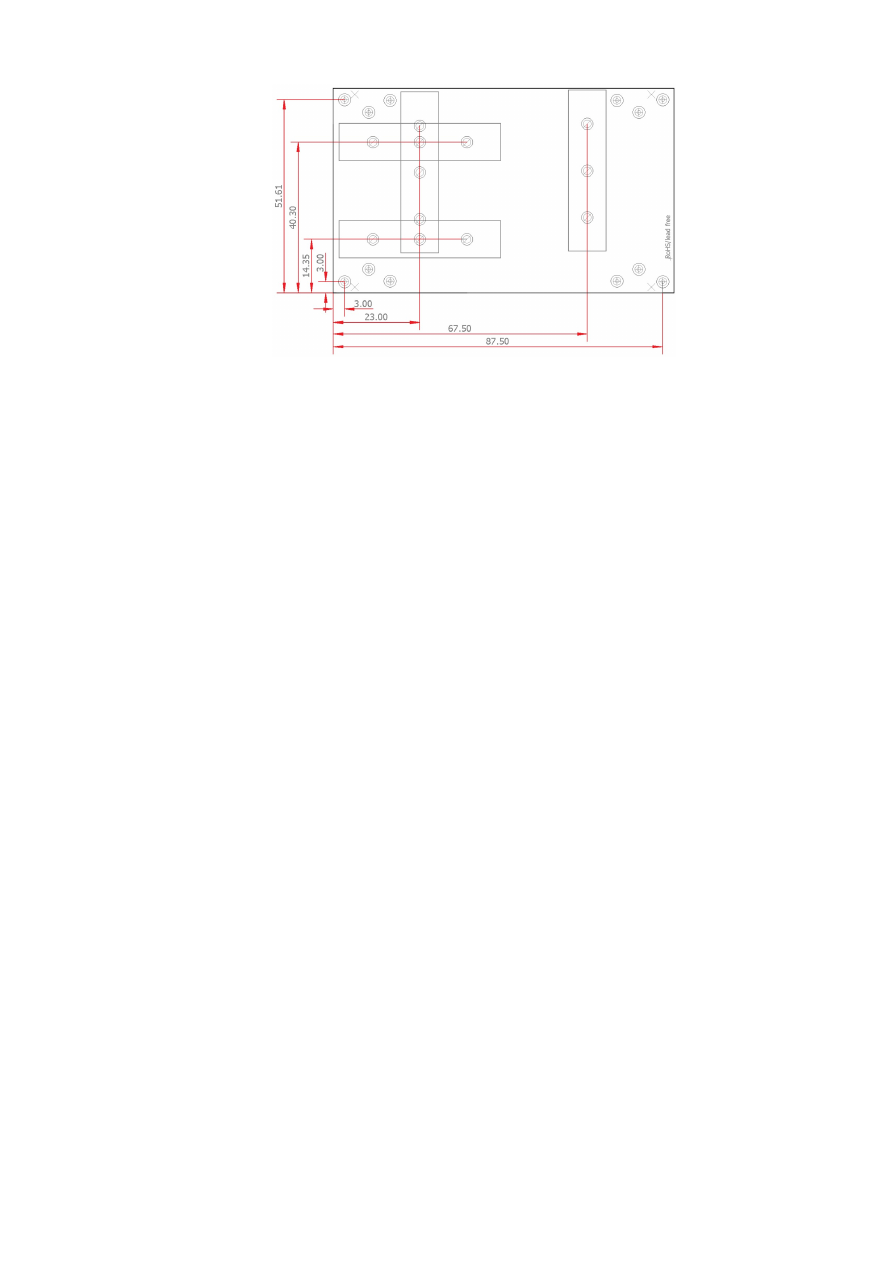
APPENDIX G – Wiring between E1703C and Raycus fiber
laser
PLEASE NOTE: this wiring scheme is a non-binding policy, it may be incorrect due to changes in connected
hardware. So in every case please check this table against specification and wiring documentation of the used
laser!
Variant using LP8 Extension Board and optional Digi I/O Extension Board for laser alarms.
Signal Name
Board
Connector / Pin
Raycus DB25 Pin
LP0
LP8 Extension Board
Pin 1
Pin 1
LP1
Pin 3
Pin 2
LP2
Pin 5
Pin 3
LP3
Pin 7
Pin 4
LP4
Pin 9
Pin 5
LP5
Pin 11
Pin 6
LP6
Pin 13
Pin 7
LP7
Pin 15
Pin 8
MO / Main
Oscillator
Pin 8
Pin 18
LaserA / Frequency
Pin 22
Pin 20
Laser Gate /
Modulation
Pin 26
Pin 19
Alarm,
one of DIn0…DIn7
Digi I/O Extension Board
Pin 4, 6, 8, 10, 12, 14, 16 or 18
Pin 16
Alarm,
one of DIn0…DIn7
Pin 4, 6, 8, 10, 12, 14, 16 or 18
Pin 21
In this wiring-scheme no GND-connections are listed, they have to be added in order to get valid and working
connections.
60

APPENDIX H – Wiring between E1703C and MaxPhotonics
MFP fiber laser
PLEASE NOTE: this wiring scheme is a non-binding policy, it may be incorrect due to changes in connected
hardware. So in every case please check this table against specification and wiring documentation of the used
laser!
Variant using E1703D Baseboard, LP8 Extension Board and optional Digi I/O Extension Board for laser alarms.
Signal Name
Board
Connector / Pin
MaxPhotonic
s DB25 Pin
LP0
LP8 Extension Board
Pin 1
Pin 1
LP1
Pin 3
Pin 2
LP2
Pin 5
Pin 3
LP3
Pin 7
Pin 4
LP4
Pin 9
Pin 5
LP5
Pin 11
Pin 6
LP6
Pin 13
Pin 7
LP7
Pin 15
Pin 8
LP8 Latch
Pin 17
Pin 9
MO / Main Oscillator
Pin 8
Pin 18
LaserA / Frequency
Pin 22
Pin 20
Laser Gate / Modulation
Pin 26
Pin 19
GND
Pin 2 or 23
Pin 10-15
Alarm,
one of DIn0…DIn7
Digi I/O Extension
Board
Pin 4, 6, 8, 10, 12, 14, 16 or 18
Pin 16
Alarm,
one of DIn0…DIn7
Pin 4, 6, 8, 10, 12, 14, 16 or 18
Pin 21
61

APPENDIX I – IDC connector pin numbering
Pin numbering of the IDC connectors (according to pinout-tables shown in hardware description sections
above) can be seen in below image:
The first pin is marked by a small arrow in connector. Second pin is below of it, counting continues column-wise.
62

APPENDIX J – Board dimensions
Board dimension drawings (baseboard plus optional extension boards), all values are given in unit mm.
Connectors, bottom view:
Connectors, top view:
Board type
C
D
E1703C Baseboard
40 mm
7,3 mm
LP8 Extension Board
40 mm
7,3 mm
Digi I/O Extension Board
34 mm
10,3 mm
Dimensions, top view:
X
– for future compatibility leave additional space of 10 mm at Ethernet
connector side of the controller
63

E170Xbase dimension drawing, all values are given in unit mm.
64

Index
A
Alive..................................................................................................................................................................................................................16
analogue output..............................................................................................................................................................................................8
B
BeamConstruct PRO license...........................................................................................................................................................10, 15
Boot...................................................................................................................................................................................................................16
C
C45 rail............................................................................................................................................................................................................30
C45 rail adapter...........................................................................................................................................................................................30
C45 rail lock...................................................................................................................................................................................................30
cggw0...............................................................................................................................................................................................................32
cginp..................................................................................................................................................................................................................34
cgip0.................................................................................................................................................................................................................32
cgipw.................................................................................................................................................................................................................33
cgnm0...............................................................................................................................................................................................................33
clcfg...................................................................................................................................................................................................................33
CO2............................................................................................................................................................................................................9, 25f.
crrrr...................................................................................................................................................................................................................33
csao0.................................................................................................................................................................................................................34
csgw0................................................................................................................................................................................................................32
csip0..................................................................................................................................................................................................................32
csipw.................................................................................................................................................................................................................33
cslgt...................................................................................................................................................................................................................34
cslmo.................................................................................................................................................................................................................34
cslp8..................................................................................................................................................................................................................34
csnm0...............................................................................................................................................................................................................33
csout.................................................................................................................................................................................................................34
cvers..................................................................................................................................................................................................................32
CW........................................................................................................................................................................................................9, 22, 26
cwcfg.................................................................................................................................................................................................................33
D
DHCP...............................................................................................................................................................................................................32
DHCP-server................................................................................................................................................................................................32
digiinit..............................................................................................................................................................................................................19
digimask..........................................................................................................................................................................................................19
digital in- and outputs................................................................................................................................................................................27
dimension drawing.....................................................................................................................................................................................63
dimensions.....................................................................................................................................................................................................63
DIN rail............................................................................................................................................................................................................30
DIN/C45 rail adapter.................................................................................................................................................................................30
DIN/C45 rail lock.........................................................................................................................................................................................30
E
E1701M.............................................................................................................................................................................................................8
E1702C_set_standby()..............................................................................................................................................................................41
e1703.cfg................................................................................................................................................................................................18, 35
e1703.fwi........................................................................................................................................................................................................18
E1703C............................................................................................................................................................................................................11
E170XC_close()............................................................................................................................................................................................36
E170XC_COMMAND_FLAG_AXIS_U..............................................................................................................................................38f.
E170XC_COMMAND_FLAG_AXIS_V..............................................................................................................................................38f.
E170XC_COMMAND_FLAG_AXIS_X..............................................................................................................................................38f.
E170XC_COMMAND_FLAG_AXIS_Y..............................................................................................................................................38f.
E170XC_COMMAND_FLAG_AXIS_Z..............................................................................................................................................38f.
E170XC_COMMAND_FLAG_DIRECT...............................................................................................................................................45
E170XC_COMMAND_FLAG_STREAM.............................................................................................................................................45
E170XC_COMMAND_FLAG_XYCORR_MIRRORX.....................................................................................................................36
65

E170XC_COMMAND_FLAG_XYCORR_MIRRORY.....................................................................................................................36
E170XC_CSTATE_ERROR................................................................................................................................................................41, 43
E170XC_CSTATE_HALTED.....................................................................................................................................................................41
E170XC_CSTATE_IS_REFERENCING................................................................................................................................................41
E170XC_CSTATE_MARKING..............................................................................................................................................................40f.
E170XC_CSTATE_MARKING|E170XC_CSTATE_PROCESSING............................................................................................40
E170XC_CSTATE_PROCESSING.......................................................................................................................................................40f.
E170XC_CSTATE_WAIT_EXTTRIGGER............................................................................................................................................41
E170XC_CSTATE_WAIT_INPUT...........................................................................................................................................................41
E170XC_delay()............................................................................................................................................................................................41
E170XC_digi_pulse()..................................................................................................................................................................................45
E170XC_digi_read()....................................................................................................................................................................................46
E170XC_digi_set_mip_output()......................................................................................................................................................18, 46
E170XC_digi_set_wet_output()......................................................................................................................................................19, 46
E170XC_digi_wait()....................................................................................................................................................................................46
E170XC_ERROR..........................................................................................................................................................................................47
E170XC_ERROR_BORD_NA..................................................................................................................................................................47
E170XC_ERROR_FILENAME.................................................................................................................................................................47
E170XC_ERROR_FILEOPEN..................................................................................................................................................................47
E170XC_ERROR_FILEWRITE................................................................................................................................................................47
E170XC_ERROR_INVALID_CARD......................................................................................................................................................47
E170XC_ERROR_INVALID_DATA.......................................................................................................................................................47
E170XC_ERROR_NO_CONNECTION...............................................................................................................................................47
E170XC_ERROR_NO_DATA_AVAILABLE........................................................................................................................................47
E170XC_ERROR_NO_MEMORY.........................................................................................................................................................47
E170XC_ERROR_NOT_SUPPORTED................................................................................................................................................47
E170XC_ERROR_OUT_OF_RANGE...................................................................................................................................................47
E170XC_ERROR_REFERENCING................................................................................................................................................44, 47
E170XC_ERROR_TRANSMISSION.....................................................................................................................................................47
E170XC_ERROR_UNKNOWN_BOARD...........................................................................................................................................47
E170XC_ERROR_UNKNOWN_FW....................................................................................................................................................47
E170XC_get_card_state().................................................................................................................................................................40, 43
E170XC_get_library_version()...............................................................................................................................................................42
E170XC_get_startstop_state()...............................................................................................................................................................40
E170XC_get_sync().....................................................................................................................................................................................39
E170XC_get_version()...............................................................................................................................................................................42
E170XC_halt_execution()........................................................................................................................................................................40
E170XC_jump_abs()...................................................................................................................................................................................38
E170XC_LASERMODE_CO2.................................................................................................................................................................37
E170XC_LASERMODE_CRF..................................................................................................................................................................38
E170XC_LASERMODE_MOPA.............................................................................................................................................................38
E170XC_LASERMODE_YAG1...............................................................................................................................................................37
E170XC_LASERMODE_YAG3...............................................................................................................................................................42
E170XC_lp8_a0().........................................................................................................................................................................................45
E170XC_lp8_write_latch().......................................................................................................................................................................44
E170XC_lp8_write_mo2()........................................................................................................................................................................45
E170XC_lp8_write()...................................................................................................................................................................................44
E170XC_mark_abs()...................................................................................................................................................................................38
E170XC_motion_reference()..................................................................................................................................................................43
E170XC_MOTION_REFSTEP_INV_SWITCH..................................................................................................................................44
E170XC_MOTION_REFSTEP_N...........................................................................................................................................................43
E170XC_MOTION_REFSTEP_P............................................................................................................................................................44
E170XC_motion_set_accel()...................................................................................................................................................................43
E170XC_motion_set_limits()..................................................................................................................................................................43
E170XC_motion_set_pos()......................................................................................................................................................................44
E170XC_motion_set_steps()...................................................................................................................................................................42
E170XC_OK..................................................................................................................................................................................................47
E170XC_open_connection().................................................................................................................................................................35f.
E170XC_release_trigger_point()...................................................................................................................................................39, 41
E170XC_set_connection()..............................................................................................................................................................35f., 39
66

E170XC_set_debug_logfile().................................................................................................................................................................35f.
E170XC_set_fpk()................................................................................................................................................................................37, 42
E170XC_set_laser_mode().......................................................................................................................................................................37
E170XC_set_laser_timing()..............................................................................................................................................................37, 41
E170XC_set_laser()....................................................................................................................................................................................38
E170XC_set_matrix()..............................................................................................................................................................................36f.
E170XC_set_password()...................................................................................................................................................................18, 35
E170XC_set_speeds()................................................................................................................................................................................37
E170XC_set_standby()....................................................................................................................................................................37f., 41
E170XC_set_sync().....................................................................................................................................................................................39
E170XC_set_trigger_point()............................................................................................................................................................35, 39
E170XC_set_xy_correction()................................................................................................................................................................36f.
E170XC_stop_execution()................................................................................................................................................................40, 43
E170XC_write_debug_logfile()..............................................................................................................................................................36
electrically insulated..................................................................................................................................................................................27
electrostatic sensitive device....................................................................................................................................................................7
Error..................................................................................................................................................................................................................16
ESD.......................................................................................................................................................................................................................7
eth......................................................................................................................................................................................................................20
Ethernet...................................................................................................................................................................................8, 11ff., 18, 20
extension.................................................................................................................................................................................................22, 26
ExtStart....................................................................................................................................................................................................39, 46
F
fiber...................................................................................................................................................................................................................25
fiber laser........................................................................................................................................................................................................54
fiber lasers......................................................................................................................................................................................................26
Firmware.........................................................................................................................................................................................................20
FPK...............................................................................................................................................................................................................9, 26
G
G0....................................................................................................................................................................................................................48f.
G1......................................................................................................................................................................................................................49
G21....................................................................................................................................................................................................................49
G28....................................................................................................................................................................................................................49
G4......................................................................................................................................................................................................................49
G90....................................................................................................................................................................................................................49
G91....................................................................................................................................................................................................................49
GRBL.................................................................................................................................................................................................................52
H
homing.............................................................................................................................................................................................................43
I
IP.................................................................................................................................................................................................................11, 18
ip0......................................................................................................................................................................................................................18
IPG..............................................................................................................................................................................................................8f., 25
IPG YLP........................................................................................................................................................................................................53ff.
IPG YLR...........................................................................................................................................................................................................57
J
JPT YDFLP.....................................................................................................................................................................................................54
L
Laser signals..................................................................................................................................................................................................25
Laser Signals..................................................................................................................................................................................................25
LaserA..............................................................................................................................................................................................................26
LaserB..............................................................................................................................................................................................................26
LaserGate.............................................................................................................................................................................................16f., 22
Latch.................................................................................................................................................................................................................26
LED....................................................................................................................................................................................................................16
LG LED.............................................................................................................................................................................................................17
Linux.................................................................................................................................................................................................................14
67

LP8.....................................................................................................................................................................................................................26
M
M3......................................................................................................................................................................................................................49
M5......................................................................................................................................................................................................................49
M700................................................................................................................................................................................................................49
M713................................................................................................................................................................................................................49
M715................................................................................................................................................................................................................49
M718................................................................................................................................................................................................................49
M719................................................................................................................................................................................................................49
M750................................................................................................................................................................................................................50
M751................................................................................................................................................................................................................50
M752................................................................................................................................................................................................................50
M753................................................................................................................................................................................................................50
M754................................................................................................................................................................................................................50
M755................................................................................................................................................................................................................50
M756................................................................................................................................................................................................................50
M757................................................................................................................................................................................................................50
M758................................................................................................................................................................................................................50
M759................................................................................................................................................................................................................50
M763................................................................................................................................................................................................................51
M764................................................................................................................................................................................................................51
M765................................................................................................................................................................................................................51
M766.........................................................................................................................................................................................................49, 51
M767.........................................................................................................................................................................................................49, 51
M768.........................................................................................................................................................................................................49, 51
M769.........................................................................................................................................................................................................49, 51
M770.........................................................................................................................................................................................................49, 51
machine network.........................................................................................................................................................................................11
marking on-the-fly......................................................................................................................................................................................28
Master Oscillator.................................................................................................................................................................................8, 25f.
MaxPhotonics...............................................................................................................................................................................................61
MaxPhotonics MFP....................................................................................................................................................................................61
Micro-SD.........................................................................................................................................................................................................17
Micro-SD-card..............................................................................................................................................................................................11
Micro-SD-Card.............................................................................................................................................................................................17
mipout..............................................................................................................................................................................................................18
MO.....................................................................................................................................................................................................................26
MO LED...........................................................................................................................................................................................................25
MOPA...............................................................................................................................................................................................................54
N
NetworkManager.......................................................................................................................................................................................14
O
Operation LED..............................................................................................................................................................................................17
Operation LEDs...........................................................................................................................................................................................11
Opto-Configuration............................................................................................................................................................................22, 27
opto-insulated..............................................................................................................................................................................................28
P
passwd.............................................................................................................................................................................................................18
Power...............................................................................................................................................................................................................11
Power LED............................................................................................................................................................................................11, 16f.
Power supply.................................................................................................................................................................................................15
Processing LED..........................................................................................................................................................................................16f.
pulse-width modulated frequency.......................................................................................................................................................26
PWM.................................................................................................................................................................................................................26
PWM frequency.............................................................................................................................................................................................9
Q
Q-Switch.....................................................................................................................................................................................................9, 26
68

R
Raycus..............................................................................................................................................................................................................60
referencing.....................................................................................................................................................................................................43
Referencing...................................................................................................................................................................................................22
Referencing LED..........................................................................................................................................................................................16
referencing speed.......................................................................................................................................................................................22
Reset.................................................................................................................................................................................................................24
RJ45..................................................................................................................................................................................................................11
RM LED............................................................................................................................................................................................................17
RunningMotion.....................................................................................................................................................................................17, 22
S
SPI.........................................................................................................................................................................................................................9
SPI G4...............................................................................................................................................................................................................58
storeinflash....................................................................................................................................................................................................17
T
T1.......................................................................................................................................................................................................................52
T1F..................................................................................................................................................................................................................48f.
tune...................................................................................................................................................................................................................19
tunemarkout.................................................................................................................................................................................................19
tunereadyout................................................................................................................................................................................................19
Type B...............................................................................................................................................................................................................53
Type D..............................................................................................................................................................................................................54
Type E...............................................................................................................................................................................................................55
Type G..............................................................................................................................................................................................................56
U
USB....................................................................................................................................................................................................................11
USB-C...................................................................................................................................................................................................8, 11, 15
User LEDs.......................................................................................................................................................................................................11
W
waveform........................................................................................................................................................................................................58
wetout......................................................................................................................................................................................................19, 50
Windows.......................................................................................................................................................................................................12f.
Y
YAG............................................................................................................................................................................................................9, 25f.
69